


<7. HART Communication>
7-6
IM 01C25W05-01EN
NOTE
It is possible to set LRV to a value greater than
URV. In such a case, the 4 to 20 mA output
signal will be inverted.
Setting conditions: LSL ≤ LRV ≤ USL
LSL ≤ URV ≤ USL
|URV – LRV| ≥ Min Span
If you set the values as shown above, change
the scale settings of the indicator so that they
match with the 4 to 20 mA output signal.
LSL: Range setting low limit
USL: Range setting high limit
7.2.2.5 Output Mode
The mode setting for the output signal and the
integral indicator (see subsection 7.2.3.6) can be
performed independently.
The output mode for the output signal is set as
specified in the order when the instrument is
shipped.
Follow the procedures below to change the mode.
• Recalling the output mode parameter (Xfer fnctn)
Recall
parameters
[Root menu] → Basic setup → DP
Signal setup →
Xfer fnctn
Select linear (Linear), square root (Sq
root), or signal characterizer (Spcl
curve).
7.2.2.6 Differential Pressure Damping
Time Constant
When the instrument is shipped, the differential
pressure damping time constant is set at 2.0
seconds.
If suffix code /CA is specified in the order, the
differential pressure damping time constant may be
set as specified at the time of order.
You can set the damping time constant to any value
within the 0.00 to 100.00 range.
To change the damping time constant, follow the
procedure below.
• Recalling the damping time constant parameter
(DP damp)
Recall
parameters
[Root menu] → Detailed setup →
Sensors → DP setup → DP damp
Enter a valid time constant in the DP damp
parameter.
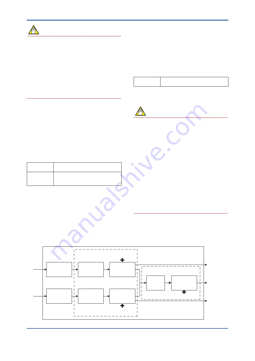
NOTE
The damping time constant set here is only for
the differential pressure transmission part.
The damping time constant for the differential
pressure (DP) is the sum of the damping
time constants for the differential pressure
transmission part, pressure transmission part,
and the capsule assembly.
The diagram in below shows the relationship of
each part. Upon shipment from the factory, the
differential pressure is assigned to PV which
shall be output via 4 to 20 mA. To change the
assignment of PV, refer to subsection 7.2.2.2.
To change the damping time constant for the
pressure of each module, refer to subsection
7.2.3.2. Refer to GS(General Specifications)
or User's Manual of each transmitter for the
damping time constant of capsule assembly.
F0724.ai
[Pres 2 damp]
[Pres 1 damp]
[DP damp]
Module 1 side
Capsule
assembly
Module 1 side
Pressure
Calculation
Module 1 side
Apply damping
for pressure
Apply dampling
for differential
pressure
Differential
pressure
calculation
Module 2 side
Capsule
assembly
Module 2 side
Pressure
Calculation
Module 2 side
Apply damping
for pressure
Pressure
input
Pressure
input
Pressure
transmission part
Module 1 side
Pressure
Differential
pressure (DP)
Module 2 side
Pressure
Digital remote sensor transmitter
Differential pressure
transmission part


