


EZZ023535
4 / 35
3.
Synchronous Control
3.1
Overview
Synchronous Control synchronizes the operation of two motors when the machine will be
operated using two independent motors.
This function can control tilting of the transported load caused by unsynchronized operation
and stress applied to the movement mechanism of the crane.
Synchronous Control has the following two modes:
Speed Synchronization Mode (SA-31 = 1)
The crane is operated by synchronizing the speed of the master and slave. The result of
multiplying the speed of the master by the gear ratio is used as the speed reference of the
slave.
Position Synchronization Mode (SA-31 = 2)
The crane is operated by synchronizing the speed and position of the master and slave.
Position Synchronization mode uses multi-function digital inputs, and the deviation in position
between the master and slave can be compensated using parameter setting values
(Advance/Retard Compensation) and detected value (Alignment).
◆ Applicable Control Modes
• Closed Loop Vector (A1-02=3)
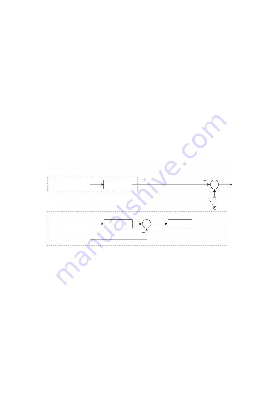
Figure 3.1 Simplified Block Diagram of Synchronous Control
3.2
Application Precautions
・
Construct a system that can monitor the READY signals and simultaneously run and stop
the motors. Additionally, simultaneously stop the motors when stopping the machine, such
as when a fault or Fast Stop occurs. If locking the motors with brakes or other equipment,
construct a system that simultaneously releases and applies the brakes. In a system where
the motors are mechanically locked, the machine may be damaged if only one motor is locked.
・
Set the gear ratio (mechanical gear ratio × digital gear ratio) to match the speed standard
for master and slave. If there is an error in the gear ratio, a deviation will occur in the positions
of the master and slave over time. The error in the mechanical gear ratio can be adjusted in
a stepless manner with the digital gear ratio. Position compensation can also be performed
with Advance/Retard Compensation and Alignment using multi-function digital inputs.
・
Set Maximum Output Frequency (E1-04) of the slave to a value that is about 10% (Position
Control Output Limit) larger than the maximum output frequency of the master.
・
In high-speed regions, the accuracy of position compensation using multi-function digital
inputs (Advance/Retard Compensation and Alignment) decreases.
Speed synchronizer
Slave
frequency
reference
Master encoder
speed
Gear calculation
Position synchronizer
Slave encoder
pulse count
Gear calculation
Master encoder
pulse count
SA-31 = 2
Position controller
Summary of Contents for CR700
Page 1: ......
Page 244: ...3 13 Test Run Checklist 244 YASKAWA SIEPC71061723A YASKAWA AC Drive CR700 Technical Manual ...
Page 422: ...7 7 Storage Guidelines 422 YASKAWA SIEPC71061723A YASKAWA AC Drive CR700 Technical Manual ...
Page 426: ...8 2 Disposal Instructions 426 YASKAWA SIEPC71061723A YASKAWA AC Drive CR700 Technical Manual ...
Page 837: ...EZZ023535 2 35 1 Revision History Revision Revised Content Date First Edition 2017 08 ...
Page 872: ...EZZ023536 2 16 Revision History Revision Revised Content Date First Edition 2017 08 ...