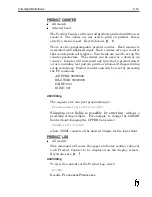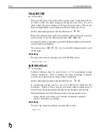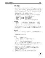
Command Definitions
Each Command Definition details function, data entry options and
ASCII string for use in external programming. The following
commands apply to 415 firmware released in fall 1997. Not all
commands will apply to every system. Custom firmware may have
additional command sets and some of the commands may operate
differently than the standard configuration.
System
Configuration
Commands
Configuration commands are used during the initial setup of the
system. Use extreme caution when changing these command as
they can have a direct influence on print quality. Before changing
these commands making notes of the default values and tracking
what has been changed is recommended.
BAUD RATE
•
Models – Quantum systems only
Accessed through keyboard, sets baud rate for Rear Port
communication for Quantum systems. Must be set to match
control device. The arrow keys select the desired baud rate.
Keystrokes to enter command are
B
A
. Use arrow keys to make
desired selection and press
R
to save.
CURVE
•
Models – All except Series 8
•
Affects selected head only (of multiple head systems)
To change the fire pulse settings, send 6 digits, which represent
the three 2-digit fields. The LEVEL command must be set to Y in
order to access the CURVE. Be sure to set the LE command back
to N when done. The fire pulse settings vary with the wax type
and Printhead type. This command is designed mainly for the
Series 7 Products for precise control of the piezoelectric crystal’s
pulse width. CURVE command sets the fire pulse settings that
control the piezoelectric drive pulses.
Contact your support representative before changing the CURVE
on a Series 6 Printer. The LEVEL command must be set to Y in
order to access CURVE. Keystrokes for CURVE command are
C u
ASCII String
To change the CURVE to 43:10:06, enter:
LEY<CR>CU431006<CR>LEN<CR>
Summary of Contents for 6100
Page 8: ...This page intentionally left blank...
Page 18: ...2 8 Application Design This page intentionally left blank...
Page 21: ...Dimensions Controller Application Design 2 11...
Page 22: ...Integrated Printhead Wax System 2 12 Application Design...
Page 55: ...Command Definitions 5 21...
Page 56: ...5 22 Command Definitions This page intentionally left blank...
Page 70: ...6 14 Installation Setup Figure 6 6...
Page 87: ...7 8 Service Figure 7 1...
Page 89: ...7 10 Service Figure 7 2...
Page 95: ...7 16 Service Figure 7 3...
Page 97: ...7 18 Service This page intentionally left blank...
Page 115: ...8 18 Removal Replacement Procedures Figure 8 7...
Page 125: ...8 28 Removal Replacement Procedures This page intentionally left blank...


