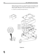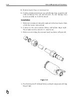
Printhead Data Cable
Some components on PCB’s are static sensitive. It is recommended
that static discharge precautions be observed when working in and
around the FoxJet controller and when handling FoxJet printed
circuit boards.
Removal
1. Turn system power off.
2. Open controller door and disconnect Printhead data cable from
J1 on the Driver board.
3. Gently remove strain relief from connector (if installed).
4. Remove nut from cable shield and gently thread the connector
the retaining nut.
5. Feed the cable out the opening in the connector panel.
6. Remove Printhead assembly from the mounting hardware and
remove the Printhead Housing Cover.
7. Remove four screws securing Printhead PCB in place.
8. Disconnect the Printhead data cable from the connector on the
Printhead PCB and unthread the nut on the cable sheath.
8-10
Removal/Replacement Procedures
Summary of Contents for 6100
Page 8: ...This page intentionally left blank...
Page 18: ...2 8 Application Design This page intentionally left blank...
Page 21: ...Dimensions Controller Application Design 2 11...
Page 22: ...Integrated Printhead Wax System 2 12 Application Design...
Page 55: ...Command Definitions 5 21...
Page 56: ...5 22 Command Definitions This page intentionally left blank...
Page 70: ...6 14 Installation Setup Figure 6 6...
Page 87: ...7 8 Service Figure 7 1...
Page 89: ...7 10 Service Figure 7 2...
Page 95: ...7 16 Service Figure 7 3...
Page 97: ...7 18 Service This page intentionally left blank...
Page 115: ...8 18 Removal Replacement Procedures Figure 8 7...
Page 125: ...8 28 Removal Replacement Procedures This page intentionally left blank...


