Wax
Reservoir
Heater
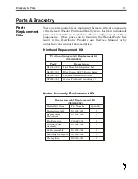
The WaxJet Heater Replacement Kit (part #X01162-002) contains
all of the parts needed for replacing the heater, as well as the
following instructions. Removing and replacing components of the
WaxJet Solid Wax System is a delicate task. During operation, the
Printhead is heated to approximately 135º C (275º
F). Make sure
that the system is thoroughly cooled down to avoid injury. Handle
the wax hose carefully to avoid damage. Read each step carefully
and follow the prescribed sequence to avoid pitfalls. The drawings
included with these instructions and shown in this section are for
illustrative purposes and are not necessarily exact replicas of the
assemblies.
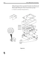
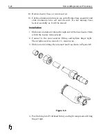
Refer to Figures 8-7 and 8-8 when using the following procedure.
Should further clarification be required, contact your Support
Representative.
Removal
1. Turn system OFF and allow to cool down. (At least 1 hour)
2. Support Printhead and remove Printhead mounting hardware.
3. Disconnect 14-pin heater cable and open filler door of Wax
System.
4. Remove 8 screws on side of Wax System and remove housing
cover (1).
5. Remove 4 screws on top insulator plate (2).
6. Remove insulator plate and carefully remove top insulation
blanket (3) from around tank assembly (4).
7. Disconnect wax line at tank fitting and disconnect hose heater
wires. Place Printhead aside. Use a wrench to hold fitting at
tank assembly while loosening hose fitting connecting nut with
another wrench (counter clockwise to loosen).
8. Do not allow fitting at tank to turn.
9. Disconnect thermal fuse and heater cable assemblies (see Figure
8-8), if installed, and skip ahead to step 13. Otherwise, continue
with the following steps.
10. Remove wax low detection wire(s) from side of reservoir.
11. Remove thermal fuse assembly (8) from side of tank.
12. Remove clamp from thermal fuse and set aside.
13.
8-16
Removal/Replacement Procedures
Summary of Contents for 6100
Page 8: ...This page intentionally left blank...
Page 18: ...2 8 Application Design This page intentionally left blank...
Page 21: ...Dimensions Controller Application Design 2 11...
Page 22: ...Integrated Printhead Wax System 2 12 Application Design...
Page 55: ...Command Definitions 5 21...
Page 56: ...5 22 Command Definitions This page intentionally left blank...
Page 70: ...6 14 Installation Setup Figure 6 6...
Page 87: ...7 8 Service Figure 7 1...
Page 89: ...7 10 Service Figure 7 2...
Page 95: ...7 16 Service Figure 7 3...
Page 97: ...7 18 Service This page intentionally left blank...
Page 115: ...8 18 Removal Replacement Procedures Figure 8 7...
Page 125: ...8 28 Removal Replacement Procedures This page intentionally left blank...


