Installation
1. Insert new disc filter into heater block wax fitting.
2. Insert new rubber seal, ensuring that shoulder of seal is flush
with the surface of the heater block.
3. Carefully remove the protective film from the new Printhead.
4. Position the Printhead with the shiny side to the faceplate and
secure with 4 new screws. Tighten snugly but avoid over
tightening.
5. Feed Printhead cable through opening in Printhead housing and
carefully connect to the Printhead PCB.
6. Remove the yellow seal from the wax inlet opening on the back of
the Printhead and secure the faceplate to the Printhead Housing
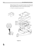
Assembly. (Figure 8-6)
7. Turn system on and Check system LED’s for proper operation of
the heating circuits.
8. Allow Printhead to heat to operating temperature. Prime/Purge
system. If leaks occur, tighten ¼ turn at a time until leaks stop.
9. Perform test print.
10. After ensuring Printhead is operating properly turn system off
and re-install Printhead housing cover and mounting hardware.
11. Re-prime Printhead and perform print test until all nozzles are
firing. Resume normal operation of printer.
Removal/Replacement Procedures
8-15
Figure 8-6
Summary of Contents for 6100
Page 8: ...This page intentionally left blank...
Page 18: ...2 8 Application Design This page intentionally left blank...
Page 21: ...Dimensions Controller Application Design 2 11...
Page 22: ...Integrated Printhead Wax System 2 12 Application Design...
Page 55: ...Command Definitions 5 21...
Page 56: ...5 22 Command Definitions This page intentionally left blank...
Page 70: ...6 14 Installation Setup Figure 6 6...
Page 87: ...7 8 Service Figure 7 1...
Page 89: ...7 10 Service Figure 7 2...
Page 95: ...7 16 Service Figure 7 3...
Page 97: ...7 18 Service This page intentionally left blank...
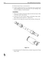
Page 115: ...8 18 Removal Replacement Procedures Figure 8 7...
Page 125: ...8 28 Removal Replacement Procedures This page intentionally left blank...


