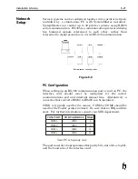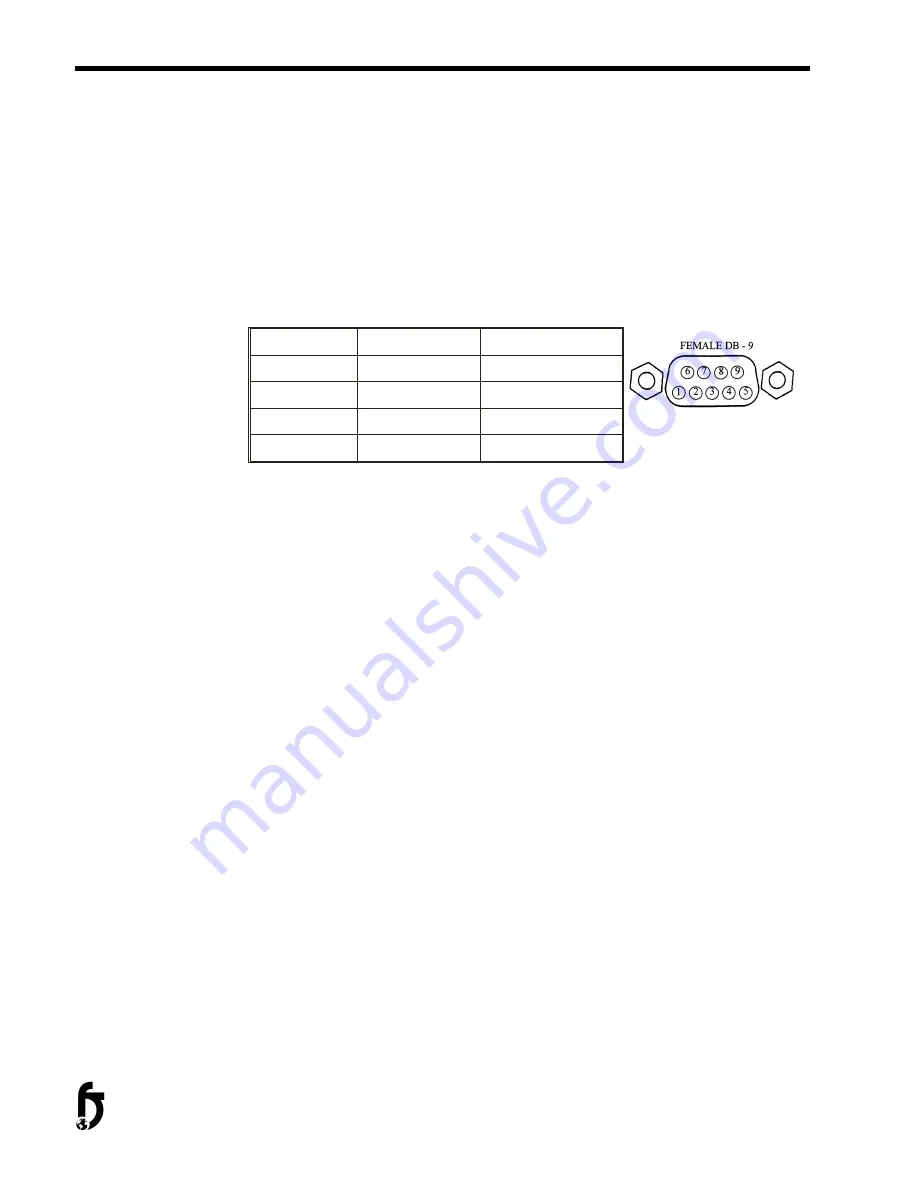
RS-485 Wiring
In a four-wire network it is necessary that one node be a master node
(PC) and all others be slave nodes (FoxJet controllers). The network
is connected so that the master node (SystemMaster PC)
communicates to all slave nodes (all FoxJet printers connected). The
slave nodes only communicate with the master node (they do not
communicate with each other). The polarity of the transmit and
receive data lines must be maintained. The table below shows the
connections for FoxJet controller networks.
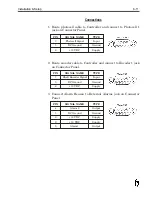
PC PORT
REAR PORT
FRONT PORT
TX (-)
PIN 3-RX(-)
PIN 25-RX(-)
TX (+)
PIN2-RX(+)
PIN 24-RX(-)
RX (-)
PIN 1-TX(-)
PIN 13-TX(-)
RX (+)
PIN9-TX(+)
PIN 12-TX(+)
Connections are made by “daisy chaining” shielded cable to the Rear
Port jack on the 6100 controller. It will be necessary to construct a
connector with dual cables since the 6100 controller has only one
serial port available for RS-485 communication.
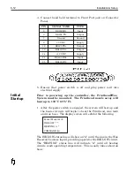
Controller Configuration
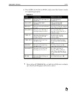
The FoxJet controller must have its CPU and Interface PCB
switches and jumpers set appropriately. The following pages show
the CPU board setting for a typical installation. Besides the
switches and jumpers, each controller must have an ID# selected
and NETWORK mode of operation enabled. The ID# is selected
from the Front Port by entering “ID” and then selecting an
identification number between 1-99 (first printer must be set to #01).
The network mode of operation is enabled by entering “NE” and
selecting Y from the hand held terminal. When the NETWORK
mode is enabled, the Front Port is capable of receiving commands,
but caution should be used. The unit can not distinguish between
commands entered through the Rear Port (PC connection) and the
hand held terminal. Conflicting commands or commands entered
while the network is communicating should be avoided. It is best
that the hand held terminal is set to the main screen when using
SystemMaster if it’s to remain connected to the controller.
•
Note: When LED 4 on the CPU board is illuminated, it
indicates that network communications is taking place.
6-22
Installation & Setup
Summary of Contents for 6100
Page 8: ...This page intentionally left blank...
Page 18: ...2 8 Application Design This page intentionally left blank...
Page 21: ...Dimensions Controller Application Design 2 11...
Page 22: ...Integrated Printhead Wax System 2 12 Application Design...
Page 55: ...Command Definitions 5 21...
Page 56: ...5 22 Command Definitions This page intentionally left blank...
Page 70: ...6 14 Installation Setup Figure 6 6...
Page 87: ...7 8 Service Figure 7 1...
Page 89: ...7 10 Service Figure 7 2...
Page 95: ...7 16 Service Figure 7 3...
Page 97: ...7 18 Service This page intentionally left blank...
Page 115: ...8 18 Removal Replacement Procedures Figure 8 7...
Page 125: ...8 28 Removal Replacement Procedures This page intentionally left blank...

