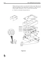
Installation
1. Inspect Interface PCB for damage that may have occurred
during shipment.
2. Place board in position and secure with fasteners.
3. Connect ribbon cable from CPU to J1.
4. Connect power cable from PSU to J2.
5. Re-connect peripheral cables to proper plugs on Connector
Panel.
6. Apply system power; ensure that the 5 green LED’s on Interface
PCB light.
7. Test all aspects of operation, particularly those involving the
peripherals connected to the Connector Panel.
8. Return to normal operations.
Removal/Replacement Procedures
8-7
Summary of Contents for 6100
Page 8: ...This page intentionally left blank...
Page 18: ...2 8 Application Design This page intentionally left blank...
Page 21: ...Dimensions Controller Application Design 2 11...
Page 22: ...Integrated Printhead Wax System 2 12 Application Design...
Page 55: ...Command Definitions 5 21...
Page 56: ...5 22 Command Definitions This page intentionally left blank...
Page 70: ...6 14 Installation Setup Figure 6 6...
Page 87: ...7 8 Service Figure 7 1...
Page 89: ...7 10 Service Figure 7 2...
Page 95: ...7 16 Service Figure 7 3...
Page 97: ...7 18 Service This page intentionally left blank...
Page 115: ...8 18 Removal Replacement Procedures Figure 8 7...
Page 125: ...8 28 Removal Replacement Procedures This page intentionally left blank...


