


362 I/O Modules
WAGO-I/O-SYSTEM 750
750-880, 750-880/025-000 ETHERNET Programmable Fieldbus Controller
Manual
Version 1.0.1
13.3.5.13 MP Bus Master Module
750-643
The MP Bus Master Module has a total of 8 bytes of user data in both the Input
and Output Process Image (6 bytes of module data and 2 bytes of control/status).
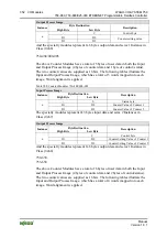
The following table illustrates the Input and Output Process Image, which have 4
words mapped into each image. Word alignment is applied.
Table 405: MP Bus Master Module 750-643
Input and Output Process Image
Byte Destination
Instance
High Byte
Low Byte
Description
C1/S1 C0/S0
extended
Control/
Status byte
Control/status
byte
D1 D0
D3 D2
n
D5 D4
Data bytes
The specialty modules represent 1x8 bytes input and output data and seize 1
Instance in Class (0x67) and 1 Instance in Class (0x68).
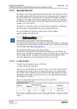
13.3.5.14
Bluetooth
®
RF-Transceiver
750-644
The size of the process image for the
Bluetooth
®
module can be adjusted to 12, 24
or 48 bytes.
It consists of a control byte (input) or status byte (output); an empty byte; an
overlayable mailbox with a size of 6, 12 or 18 bytes (mode 2); and the
Bluetooth
®
process data with a size of 4 to 46 bytes.
Thus, each
Bluetooth
®
module uses between 12 and 48 bytes in the process image.
The sizes of the input and output process images are always the same.
The first byte contains the control/status byte; the second contains an empty byte.
Process data attach to this directly when the mailbox is hidden. When the mailbox
is visible, the first 6, 12 or 18 bytes of process data are overlaid by the mailbox
data, depending on their size. Bytes in the area behind the optionally visible
mailbox contain basic process data. The internal structure of the
Bluetooth
®
process data can be found in the documentation for the
Bluetooth
®
750-644 RF
Transceiver.
The mailbox and the process image sizes are set with the startup tool WAGO-I/O-
CHECK
.


