


360 I/O Modules
WAGO-I/O-SYSTEM 750
750-880, 750-880/025-000 ETHERNET Programmable Fieldbus Controller
Manual
Version 1.0.1
Output Process Image
Byte Destination
Instance
High Byte
Low Byte
Description
reserved C0
reserved
Control
byte
C0
D1 D0
D3 D2
D5 D4
Process data*) / Mailbox**)
C3 D6
Control
byte
C3
Process data*) /
reserved**)
n
C1
C2
Control byte C1 Control byte C2
*)
Cyclic process image (Mailbox disabled)
**)
Mailbox process image (Mailbox activated)
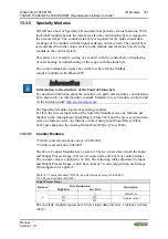
The specialty modules represent 1x12 bytes input and output data and seize 1
Instance in Class (0x67) and 1 Instance in Class (0x68).
13.3.5.10 RTC Module
750-640
The RTC Module has a total of 6 bytes of user data in both the Input and Output
Process Image (4 bytes of module data and 1 byte of control/status and 1 byte ID
for command). The following table illustrates the Input and Output Process
Image, which have 3 words mapped into each image. Word alignment is applied.
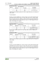
Table 402: RTC Module 750-640
Input and Output Process Image
Byte Destination
Instance
High Byte
Low Byte
Description
ID C/S
Command
byte
Control/status
byte
D1 D0
n
D3 D2
Data bytes
The specialty modules represent 1x6 bytes input data and seize 1 Instance in Class
(0x67).and seize 1 Instance in Class (0x68).


