Parameter Description VD120 Series Inverter User Manual
-
126
-
Output
current
Timing braking
frequency
DO timing
braking
output Fb-48
Timing braking time Fb-49
Time(t)
Time(t)
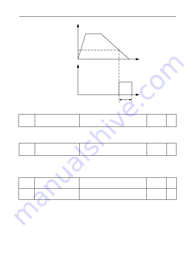
Fig 6-29 Schematic diagram of timing braking action
Fb-50
Terminal Jog Priority
0: Disabled
1: Enabled
1
○
This parameter is used to set whether the highest priority of terminal jog function.
When the terminal jog priority is valid, if terminal jog command appeared in the process of running,
the inverter switch to a terminal jog running state.
Fb-51
Swing Frequency Setting
Method
0: Relative to center frequency
1: Relative to max frequency
0
○
Through this parameter to determine the benchmark of the swing.
0: relative center frequency (F0-05 frequency source), for variable amplitude system. The amplitude
of the swing is varied with the change of the central frequency (setting frequency).
1: relative maximum frequency (F0-10), as the swing system, swing fixed.
Fb-52
Swing Frequency
Amplitude
0.0%~100.0%
0.0%
○
Fb-53
Jumping Frequency
Amplitude
0.0%~50.0%
0.0%
○
Through this parameter to determine the value of the amplitude and jumping frequency.
When setting swing relative to the center frequency (Fb-51=0), swing AW = frequency source F0-5 x
swing amplitude Fb - 52. When setting swing relative to the maximum frequency (Fb-51=1), swing
AW = maximum frequency F0-10 x swing amplitude Fb - 52.
Jumping frequency range for the swing frequency runtime, jumping frequency relative to the
frequency percentage of the swing, i.e., jumping frequency=swing AW * jumping frequency amplitude
Fb-53. If selection swing relative to the center frequency (Fb-51=0), jumping frequency is the variable
value. If selection swing relative to the maximum frequency (Fb-51=1), jumping frequency is a fixed
value.
Swing running frequency is constraints by the frequency upper limit and frequency lower limit.
Summary of Contents for VD120 Series
Page 2: ......


