183
A
PPLICATION
L
IQU
ID
R
ATE
C
ONTROL
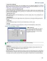
• Control Valve Settings
Opens the Control Valve Settings screen, which displays control valve settings for PWM, Servo, Calibrated
Reflow and Ramsey Valve Controls. For more information, see below or for more settings see
Settings - Servo, Calibrated Reflow and Ramsey Valve” on page 184
.
• Close Flow Control Valve When Rate Off
When this is selected, the controlling system shuts down when there is either a zero rate in the field or when
entering an already-applied area. When unchecked, the controlling system remains in the last known state
when the sections are shut off.
• Auxiliary Valve 1 & 2
When all boom sections are off, this setting closes or opens an auxiliary valve. Choose settings for up to
two auxiliary valves.
• Allowable Error
Determines the percent of error that is allowed prior to the product control system making any flow rate
changes.
• Threshhold
The user-defined percentage of actual rate error allowed before an alarm sounds.
• Timeout
The number of seconds that an actual rate falls out of the error threshold before an alarm sounds.
Control Valve Settings - PWM
• PWM Frequency
The frequency that the PWM control valve is
pulsed at. Settings can be found from the
manufacturer of the valve. Typical settings
range from 100-125 Hz.
Note: See PWM valve manufacturer information for recommended settings.
• PWM Gain
Determines how aggressively the control valve responds when making rate change adjustments. The
higher the value the more aggressive the system response is.
• Zero Flow Offset
Represents the maximum duty cycle that is sent to the control valve without producing any hydraulic flow
from the PWM valve. Using too high of a Zero Flow Offset value can cause the product control system to
not properly control low rates. See the PWM valve manufacturer information for recommended settings.
Control Valve Settings
PWM 12 volt
Control Valve:
PWM Frequency
PWM Gain
Zero Flow Offset
PWM Standby
50
30
800
100
Allowable
Error
2 %
Summary of Contents for ag leader
Page 1: ...Operators Manual Firmware Version 5 4 Ag Leader PN 4002722 Rev G ...
Page 2: ...Firmware Version 5 4 ...
Page 20: ...6 Firmware Version 5 4 ...
Page 38: ...24 Firmware Version 5 4 For more information see Legend Settings on page 52 ...
Page 55: ...41 SETUP M ANAGEMENT S ETUP Remove button Press to remove a business ...
Page 56: ...42 Firmware Version 5 4 ...
Page 78: ...64 Firmware Version 5 4 ...
Page 82: ...68 Firmware Version 5 4 Press to Export All Log files Export All Log Files ...
Page 84: ...70 Firmware Version 5 4 ...
Page 94: ...80 Firmware Version 5 4 ...
Page 108: ...94 Firmware Version 5 4 ...
Page 140: ...126 Firmware Version 5 4 ...
Page 154: ...140 Firmware Version 5 4 ...
Page 158: ...144 Firmware Version 5 4 ...
Page 162: ...148 Firmware Version 5 4 ...
Page 222: ...208 Firmware Version 5 4 ...
Page 244: ...230 Firmware Version 5 4 ...
Page 260: ...246 Firmware Version 5 4 ...
Page 290: ...276 Firmware Version 5 4 ...
Page 304: ...290 Firmware Version 5 4 ...


