Strata CTX100 Installation
Installing the CTX100 Cabinet
2-10
Strata CTX I&M 10/02
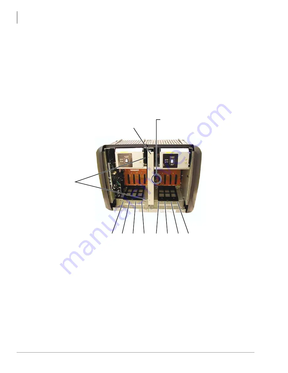
10. Finish by securing the Expansion Cabinet to the Base cabinet with the two screws in front of
the cabinets where they join together. The expansion cabinet left-side flange fits over the Base
cabinet right side flange (see
Figure 2-7
).
11. On the AMAU motherboard of the Expansion Cabinet, flip open the two data ribbon locks,
plug in the data ribbon and close the locks. The data ribbon cable should now be connected to
the Base and Expansion cabinets.
12. Install PCBs into the Expansion Cabinet; follow the instructions in
“Step 10: Install Other
PCBs into the Cabinet(s)”
.
Note
The Base Cabinet DC power switch will be the master control for turning the DC power of
both cabinets On/Off.
13. Attach the outside covers on the Expansion Cabinet.
Figure 2-7
Base and Expansion Cabinet Interior
Flip open locks to plug in data cable.
Push locks closed once cable is
plugged in. Make sure locks are
closed.
Left side of Expansion Cabinet fits
over the right side of the Base
Cabinet.
S101 S102 S103 S104 S105 S106 S107 S108
5969
2 - Screws
Summary of Contents for Strata CTX100
Page 16: ...Introduction Related Documents Media xii Strata CTX I M 10 02 ...
Page 94: ...Strata CTX100 Installation Installing the CTX100 Cabinet 2 24 Strata CTX I M 10 02 ...
Page 150: ...Strata CTX670 Installation Remote Expansion Cabinet Unit 3 56 Strata CTX I M 10 02 ...
Page 188: ...PCB Installation Network Requirements 4 38 Strata CTX I M 10 02 ...
Page 238: ...T1 Loop Back Testing 6 12 Strata CTX I M 10 02 ...
Page 310: ...Station Apparatus 2000 series Telephones 8 48 Strata CTX I M 10 02 ...
Page 342: ...Peripheral Installation Station Message Detail Recording SMDR 9 32 Strata CTX I M 10 02 ...


