No.
6
Item
Fan speed
selection
Outline of specifications
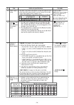
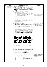
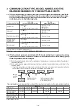
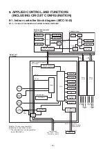
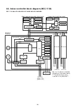
1) By the command from remote control, fan speed is
changed. ((HH), (H+), (H), (L+), (L) or [AUTO])
2) When the fan speed mode [AUTO] is selected, the fan
speed varies by the difference between TA and Ts.
<COOL>
Remarks
HH > H+ > H > L+ > L > UL
Depending on the remote
controller used, (H+) and (L+)
cannot be selected.
For Floor Standing Concealed
Type,or Floor Standing Cabinet
Type, (HH), (H), (L) or [AUTO]
can be selected regardless of
remote controller models.
• Fan speed mode [AUTO] in case when remote
controller sensor works is equal to that in case when
indoor unit sensor works.
• If the fan speed has been changed once, it is not
changed for 3 minutes. However when the air volume
is changed, the fan speed changes.
• When cooling operation has started, select a down-
ward slope for the fan speed, that is, the high position.
• If the temperature is just on the difference boundary,
the fan speed does not change.
<HEAT>
Value in the parentheses indicates one when sensor of
the remote controller works.
Value without parentheses indicates one when sensor
of the indoor unit sensor works.
• If the fan speed has been changed once, it is not
changed for 1 minute. However when the fan speed
changed, the fan speed changes.
• When heating operation has started, select an upward
slope for the fan speed, that is, the high position.
• If the temperature is just on the difference boundary,
the fan speed does not change.
• In TC2
≥
60˚C, the fan speed increases by 1 step.
TA (˚C)
+3.0
+2.5
+2.0
+1.5
+1.0
+0.5
Tsc
–0.5
HH
<HH>
H+ <HH>
H <HH>
L+ <H+>
L <H>
L <H>
L <L+>
< > : Indicate automatic cooling.
D
C
B
A
E
F
G
TA (˚C)
(+0.5) +1.0
(0) Tsh
(+0.5) +1.0
(-1.0) -2.0
(-1.5) -3.0
(-2.0) -4.0
L <L+>
L+ <H>
H <H+>
HH
<HH>
H+
<HH>
E
D
C
B
A
Body sensor works.
Remote controller sensor works.
< > : Indicate automatic heating.
Code No. [32]
0000: Indoor unit sensor
(Main unit)
0001: Remote controller
sensor
TC2:
Temperature of indoor
heat exchanger sensor
- 70 -
Summary of Contents for MMC-UP0151HP-E
Page 41: ...2 2 Ceiling type MMC UP0151HP E TR MMC UP0181HP E TR 41 ...
Page 42: ...MMC UP0241HP E TR MMC UP0271HP E TR 6 4 12 7 42 ...
Page 43: ...MMC UP0361HP E TR MMC UP0481HP E TR MMC UP0561HP E TR 43 ...
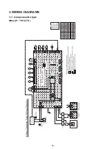
Page 58: ...3 WIRING DIAGRAMS 3 1 4 way cassette type MMU UP HP E TR 58 ...
Page 59: ...3 2 Ceiling type MMC UP HP E TR 59 ...
Page 60: ...3 3 Concealed Duct Standard type MMD UP BHP E TR 60 ...
Page 61: ...3 4 Concealed Duct High Static Pressure type MMD UP HP E TR 61 ...
Page 62: ...Concealed Duct High Static Pressure type MMD UP HP E TR 62 ...
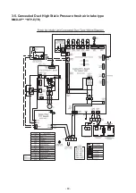
Page 63: ...3 5 Concealed Duct High Static Pressure fresh air intake type MMD UP HFP E TR 63 ...
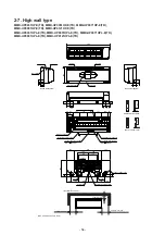
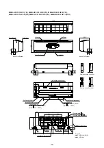
Page 65: ...3 7 High wall type MMK UP HP E TR 65 ...
Page 249: ...MMU UP0361HP E TR MMU UP0481HP E TR MMU UP0561HP E TR 268 267 213 214 249 ...
Page 252: ...12 2 Ceiling type MMC UP0151HP E TR MMC UP0181HP E TR 025 024 252 ...
Page 254: ...MMC UP0241HP E TR MMC UP0271HP E TR 029 028 254 ...
Page 256: ...MMC UP0361HP E TR MMC UP0481HP E TR MMC UP0561HP E TR 051 028 027 256 ...
Page 261: ...MMD UP0151BHP E TR MMD UP0181BHP E TR 240 239 238 233 235 261 ...
Page 263: ...MMD UP0241BHP E TR MMD UP0271BHP E TR MMD UP0301BHP E TR 240 239 238 233 235 263 ...
Page 265: ...MMD UP0361BHP E TR MMD UP0481BHP E TR MMD UP0561BHP E TR 240 239 238 233 235 265 ...

