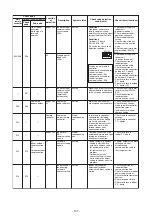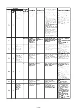
(Check code detected by remote controller)
Check code
Display of receiving unit
Typical trouble site
Description of trouble
Outdoor 7-segment display
Indicator light block
Sub-code
Flash
E01
–
–
No master remote control,
failure remote control
communication (reception)
Signals cannot be received from indoor unit;
master remote control has not been set
(including two remote control).
E02
–
–
Failure remote control
communication (transmission) Signals cannot be transmitted to indoor unit.
E09
–
–
Duplicated master remote
control
Both remote controls have been set as
master remote control in two remote control
(alarm and shutdown for header unit and
continued operation for follower unit)
Operation Timer Ready
Remote control
Check code
Display of receiving unit
Typical trouble site
Description of trouble
Central control
Outdoor 7-segment display
Indicator light block
Sub-code
Flash
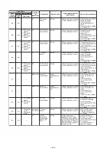
C05
–
–
No indication (when
main remote control
also in use)
Failure central control
communication (transmission)
Central control device is unable to transmit
signal due to duplication of central control
device
C06
–
–
Failure central control
communication (reception)
Central control device is unable to receive
signal.
C12
–
–
–
Bracket alarm for general-
purpose device control
interface
Device connected to general-purpose device
control interface is trouble.
P30
(L20)
(L20 is displayed.)
Communication Link
–
–
• Duplication addresses of indoor units in
central control device
• With the combination of air conditioning
system, the indoor unit may detect the
check code of L20
Operation Timer Ready
(Check code detected by central control device)
Note:
The same trouble, e.g. a communication trouble, may result in the display of different check codes
depending on the device that detects it. Moreover, check codes detected by the main remote controller /
central control device do not necessarily have a direct impact on air conditioner operation.
Flow selector unit (FS unit) Relation
(Check code detected by indoor unit)
E17
–
–
Communication trouble between
indoor unit (s) and FS unit (s)
There is no communication from FS unit(s)
Check code
Display of receiving unit
Typical trouble site
Description of trouble
Outdoor 7-segment display
Indicator light block
Sub-code
Flash
Operation Timer Ready
Main remote control
J03
–
–
More than one FS units have been set up in
one refrigerant line.
Duplicated FS units
J10
–
–
FS unit has been shutdown in one refrigerant
line due to detection of overflow
FS unit overflow trouble
L12
L12
–
FS unit(s) system trouble
FS unit(s) outside the application setting
J11
–
–
FS unit temperature sensor (TCS) has been
open/short-circuited.
FS unit temperature sensor
(TCS) trouble
- 126 -
Summary of Contents for MMC-UP0151HP-E
Page 41: ...2 2 Ceiling type MMC UP0151HP E TR MMC UP0181HP E TR 41 ...
Page 42: ...MMC UP0241HP E TR MMC UP0271HP E TR 6 4 12 7 42 ...
Page 43: ...MMC UP0361HP E TR MMC UP0481HP E TR MMC UP0561HP E TR 43 ...
Page 58: ...3 WIRING DIAGRAMS 3 1 4 way cassette type MMU UP HP E TR 58 ...
Page 59: ...3 2 Ceiling type MMC UP HP E TR 59 ...
Page 60: ...3 3 Concealed Duct Standard type MMD UP BHP E TR 60 ...
Page 61: ...3 4 Concealed Duct High Static Pressure type MMD UP HP E TR 61 ...
Page 62: ...Concealed Duct High Static Pressure type MMD UP HP E TR 62 ...
Page 63: ...3 5 Concealed Duct High Static Pressure fresh air intake type MMD UP HFP E TR 63 ...
Page 65: ...3 7 High wall type MMK UP HP E TR 65 ...
Page 249: ...MMU UP0361HP E TR MMU UP0481HP E TR MMU UP0561HP E TR 268 267 213 214 249 ...
Page 252: ...12 2 Ceiling type MMC UP0151HP E TR MMC UP0181HP E TR 025 024 252 ...
Page 254: ...MMC UP0241HP E TR MMC UP0271HP E TR 029 028 254 ...
Page 256: ...MMC UP0361HP E TR MMC UP0481HP E TR MMC UP0561HP E TR 051 028 027 256 ...
Page 261: ...MMD UP0151BHP E TR MMD UP0181BHP E TR 240 239 238 233 235 261 ...
Page 263: ...MMD UP0241BHP E TR MMD UP0271BHP E TR MMD UP0301BHP E TR 240 239 238 233 235 263 ...
Page 265: ...MMD UP0361BHP E TR MMD UP0481BHP E TR MMD UP0561BHP E TR 240 239 238 233 235 265 ...

