WARNING
• Since high voltages pass through the electrical parts, turn off the power without fail before proceeding with
the repairs.
Electric shocks may occur if the power plug is not disconnected.
• After the repairs have been completed (after the front panel and cabinet have been installed), perform a
test run, and check for smoking, unusual sounds and other abnormalities.
If this check is omitted, a fire and/or electric shocks may occur.
Before proceeding with the test run, install the front panel and cabinet.
• Ensure that the following steps are taken when doing repairs on the refrigerating cycle.
1. Do not allow any naked flames in the surrounding area.
If a gas stove or other appliance is being used, extinguish the flames before proceeding.
If the flames are not extinguished, they may ignite any oil mixed with the refrigerant gas.
2. Do not use welding equipment in an airtight room.
Carbon monoxide poisoning may result if the room is not properly ventilated.
3. Do not bring welding equipment near flammable objects.
Flames from the equipment may cause the flammable objects to catch fire.
•
If keeping the power on is absolutely unavoidable while doing a job such as inspecting the cir-
cuitry, wear rubber gloves to avoid contact with the live parts.
Electric shocks may be received if the live parts are touched.
High-voltage circuits are contained inside this unit.
Proceed very carefully when conducting checks since directly touching the parts on the control circuit
board may result in electric shocks.
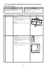
No. Part name
Procedure
Remarks
①
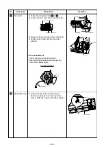
Front panel
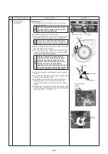
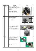
1) Stop operation of the air conditioner
and turn off the main power supply.
2) Grip the air inlet grille by two hands
at the handle positions.
3) Pull the air inlet grille as the
arrow direction and remove the rope
from the hook of front panel.
4) Remove screws for front panel. (4 pcs)
Hook of front panel
Rope
Air inlet grille
4) Screws of front
panel (4 pcs)
11-
6
.
Console type
- 222 -
Summary of Contents for MMC-UP0151HP-E
Page 41: ...2 2 Ceiling type MMC UP0151HP E TR MMC UP0181HP E TR 41 ...
Page 42: ...MMC UP0241HP E TR MMC UP0271HP E TR 6 4 12 7 42 ...
Page 43: ...MMC UP0361HP E TR MMC UP0481HP E TR MMC UP0561HP E TR 43 ...
Page 58: ...3 WIRING DIAGRAMS 3 1 4 way cassette type MMU UP HP E TR 58 ...
Page 59: ...3 2 Ceiling type MMC UP HP E TR 59 ...
Page 60: ...3 3 Concealed Duct Standard type MMD UP BHP E TR 60 ...
Page 61: ...3 4 Concealed Duct High Static Pressure type MMD UP HP E TR 61 ...
Page 62: ...Concealed Duct High Static Pressure type MMD UP HP E TR 62 ...
Page 63: ...3 5 Concealed Duct High Static Pressure fresh air intake type MMD UP HFP E TR 63 ...
Page 65: ...3 7 High wall type MMK UP HP E TR 65 ...
Page 249: ...MMU UP0361HP E TR MMU UP0481HP E TR MMU UP0561HP E TR 268 267 213 214 249 ...
Page 252: ...12 2 Ceiling type MMC UP0151HP E TR MMC UP0181HP E TR 025 024 252 ...
Page 254: ...MMC UP0241HP E TR MMC UP0271HP E TR 029 028 254 ...
Page 256: ...MMC UP0361HP E TR MMC UP0481HP E TR MMC UP0561HP E TR 051 028 027 256 ...
Page 261: ...MMD UP0151BHP E TR MMD UP0181BHP E TR 240 239 238 233 235 261 ...
Page 263: ...MMD UP0241BHP E TR MMD UP0271BHP E TR MMD UP0301BHP E TR 240 239 238 233 235 263 ...
Page 265: ...MMD UP0361BHP E TR MMD UP0481BHP E TR MMD UP0561BHP E TR 240 239 238 233 235 265 ...

