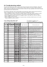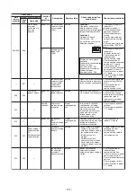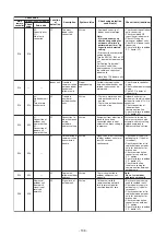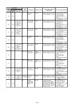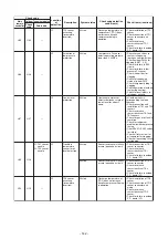
Check code
Display of receiving unit
Typical problem site
Description of problem
Outdoor 7-segment display
Central
control or
main remote
controller
display
Indicator light block
Sub-code
Flash
E06
Number of indoor units from which
signal is received normally
Signal lack of indoor unit
E06
Indoor unit initially communicating normally fails to
return signal (reduction in number of indoor units
connected).
E07
–
(E04)
Indoor-outdoor
communication circuit
trouble
Signal cannot be transmitted to indoor units
(
indoor units left without communication from
outdoor unit).
E08 Duplicated indoor address
(E08)
Duplicated indoor address
More than one indoor unit are assigned same
address (also detected at indoor unit end).
E12
01: Indoor-outdoor communication
02: Outdoor-outdoor
communication
E12
Automatic address starting
trouble
• Indoor automatic address setting is started while
automatic address setting for equipment in other
refrigerant line is in progress.
• Outdoor automatic address setting is started
while automatic address setting for indoor units
is in progress.
E15
–
E15
Indoor unit not found
during automatic address
setting
Indoor unit fails to communicate while automatic
address setting for indoor units is in progress.
E16
00: Capacity over
01: Number of units connected
E16
Too many indoor units
connected/capacity over
Combined capacity of indoor units is too large.
The maximum combined of indoor units shown in
the specification table.
E19
00: No header unit
02: Two or more header units
E19
Trouble in number of
outdoor header units
There is no or more than one outdoor header unit
in one refrigerant line.
E20
01: Connection of outdoor unit from
other refrigerant line
02: Connection of indoor unit from
other refrigerant line
E20
Connection to other
refrigerant line found
during automatic address
setting
Indoor unit from other refrigerant line is detected
while indoor automatic address setting is in
progress.
E23
–
E23
Outdoor-outdoor
communication
transmission trouble
Signal cannot be transmitted to other outdoor
units.
E25
–
E25
Duplicated follower
outdoor address
There is duplication in outdoor addresses set
manually.
E26
Address of outdoor unit from which
signal is not received normally
E26
Signal lack of outdoor unit
Follower outdoor unit initially communicating
normally fails to do so (reduction in number of
follower outdoor units connected).
Outdoor follower unit
trouble
E28
E28
O
Detected outdoor unit No.
utdoor header unit detects trouble relating to
follower outdoor unit (detail displayed on follower
outdoor unit).
E31
E31
There is no communication between P.C. boards
in inverter box.
–
F04
F04
Outdoor discharge
temperature sensor (TD1)
trouble
Outdoor discharge temperature sensor (TD1) has
been open/short-circuited.
F05
–
F05
Outdoor discharge
temperature sensor (TD2)
trouble
Outdoor discharge temperature sensor (TD2) has
been open/short-circuited.
F06
01: TE1 sensor
02: TE2 sensor
03: TE3 sensor
Outdoor heat exchanger
liquid side temperature
sensor (TE1, TE2, TE3)
trouble
Outdoor heat exchanger liquid side temperature
sensors (TE1, TE2, TE3) have been open/
short-circuited.
F07
Outdoor liquid temperature
sensor (TL1,TL2,TL3)
trouble
Outdoor liquid temperature sensor (TL1,TL2,TL3)
has been open/short-circuited.
–
F08
F06
F07
F08
ALT
ALT
ALT
ALT
ALT
Outdoor outside air
temperature sensor (TO)
trouble
Outdoor air temperature sensor (TO) has been
open/short-circuited.
Outdoor heat exchanger
gas side temperature
sensor (TG1, TG2, TG3)
trouble
Outdoor heat exchanger gas side temperature
sensors (TG1, TG2, TG3) have been open/
short-circuited.
Operation
Timer Ready
Circle (O): Trouble P.C. board
01: TL1 sensor
02: TL2 sensor
03: TL3 sensor
F0
F09
ALT
9
01: TG1 sensor
02: TG2 sensor
03: TG3 sensor
P.C. board communication
trouble
Sub MCU
communication trouble
80 : Communication trouble between
MCU and Sub MCU
: Lighting, : Flashing, : Goes off
ALT.: Flashing is alternately when there are two flashing LED
SIM: Simultaneous flashing when there are two flashing LED
P.C.board
Compressor Fan Motor
01
02
03
08
09
0A
0B
10
1
O
O
O
O
2
O
O
O
O
1
O
O
O
O
2
O
P.C.board
Compressor Fan Motor
11
12
13
18
19
1A
1B
1
O
O
O
O
2
O
O
O
O
2
O
O
O
O
O
O
O
1
List of Check Codes (Outdoor Unit)
(Check code detected by outdoor interface - typical examples)
If "HELLO" is displayed on the oudoor 7-segment for 1 minute or more, turn off the power supply once and
then turn on the power supply again after passage of 30 seconds or more. When the same symptom appears,
it is considered there is a possibility of I/F board trouble.
- 127 -
Summary of Contents for MMC-UP0151HP-E
Page 41: ...2 2 Ceiling type MMC UP0151HP E TR MMC UP0181HP E TR 41 ...
Page 42: ...MMC UP0241HP E TR MMC UP0271HP E TR 6 4 12 7 42 ...
Page 43: ...MMC UP0361HP E TR MMC UP0481HP E TR MMC UP0561HP E TR 43 ...
Page 58: ...3 WIRING DIAGRAMS 3 1 4 way cassette type MMU UP HP E TR 58 ...
Page 59: ...3 2 Ceiling type MMC UP HP E TR 59 ...
Page 60: ...3 3 Concealed Duct Standard type MMD UP BHP E TR 60 ...
Page 61: ...3 4 Concealed Duct High Static Pressure type MMD UP HP E TR 61 ...
Page 62: ...Concealed Duct High Static Pressure type MMD UP HP E TR 62 ...
Page 63: ...3 5 Concealed Duct High Static Pressure fresh air intake type MMD UP HFP E TR 63 ...
Page 65: ...3 7 High wall type MMK UP HP E TR 65 ...
Page 249: ...MMU UP0361HP E TR MMU UP0481HP E TR MMU UP0561HP E TR 268 267 213 214 249 ...
Page 252: ...12 2 Ceiling type MMC UP0151HP E TR MMC UP0181HP E TR 025 024 252 ...
Page 254: ...MMC UP0241HP E TR MMC UP0271HP E TR 029 028 254 ...
Page 256: ...MMC UP0361HP E TR MMC UP0481HP E TR MMC UP0561HP E TR 051 028 027 256 ...
Page 261: ...MMD UP0151BHP E TR MMD UP0181BHP E TR 240 239 238 233 235 261 ...
Page 263: ...MMD UP0241BHP E TR MMD UP0271BHP E TR MMD UP0301BHP E TR 240 239 238 233 235 263 ...
Page 265: ...MMD UP0361BHP E TR MMD UP0481BHP E TR MMD UP0561BHP E TR 240 239 238 233 235 265 ...


