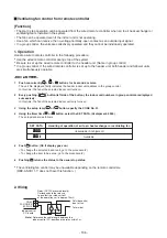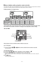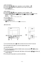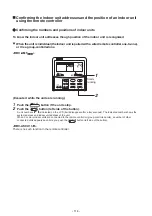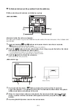
Auto-off feature control
[Function]
• This function controls the indoor units individually. It is used when the start operation from outside is
unnecessary but the stop operation is necessary.
• A card switch box or card lock helps protect customers from forgetting to turn off the indoor unit.
(not including the following Card Input 3)
• It is connected with connector on the indoor control P.C. board, and switched with the Code No. and jumper
wire setup for use.
• Available connectors are CN61 or CN73. For models without CN73, CN4 on the optional Application control
kit (TCB-PCUC2E) can be used.
* Leaving-ON prevention control cannot be set with both CN61 and CN73 (CN4).
If both of them are set, CN73 (CN4) setting automatically turns to a factory default.
[Setup method]
(1) Wiring
(2)
Code (DN) setup
Set Code (DN) according to “8-
6
. Method to set indoor unit function DN code”.
1
2
1
2
3
4
3
4
5
6
5
6
CN61
T10
(YEL)
* In the figure, the contact indicates
a status that the card is taken out.
Power supply
Outside contact (Card switch box, etc: Procured locally)
Relay (procured locally)
Connecting to the CN61 connector
NOTE)
Determine the cable length between the indoor control P.C. board and the relay within 3m.
Indoor control P.C. board
1
2
1
2
CN4
EXCT
(RED)
* In the figure, the contact indicates
a status that the card is taken out.
Power supply
Outside contact (Card switch box, etc: Procured locally)
Relay (procured locally)
Connecting to the Application control kit (TCB-PCUC2E, connector : CN4)
NOTE)
Determine the cable length between the indoor control P.C. board and the relay within 3m.
Application control kit
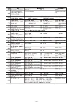
Connector Jumper wire (J01) Code No. (DN)
Set data
Function
CN61
CN73
(CN4)
Short-circuit
(Factory default)
Short-circuit
(Factory default)
or
Open-circuit (cut)
Open-circuit (cut)
002E
000b
0000 (Factory default)
0001
0003
0005
0000 (Factory default)
0001
0003
0000 (Factory default)
0002
0004
0007
0008
0009
"HA normal setup" (pulse)
"Card Input 1" setup
"Card Input 2" setup
"Card Input 5" setup
"HA normal setup" (Static)
"Card Input 3" setup
"Card Input 4" setup
"EXCT demand" setup (Forced thermostat-OFF)
"Card Input 3" setup
"Card Input 4" setup
"Card Input 5" setup
"Card Input 1" setup
"Card Input 2" setup
* If you set “Card Input 1 to 5” for Code No. of CN61 and CN73, Code No. 000b setup becomes unavailable
and the functions of Card Input 1 to 5 in CN73 cannot be used.
- 107 -
Summary of Contents for MMC-UP0151HP-E
Page 41: ...2 2 Ceiling type MMC UP0151HP E TR MMC UP0181HP E TR 41 ...
Page 42: ...MMC UP0241HP E TR MMC UP0271HP E TR 6 4 12 7 42 ...
Page 43: ...MMC UP0361HP E TR MMC UP0481HP E TR MMC UP0561HP E TR 43 ...
Page 58: ...3 WIRING DIAGRAMS 3 1 4 way cassette type MMU UP HP E TR 58 ...
Page 59: ...3 2 Ceiling type MMC UP HP E TR 59 ...
Page 60: ...3 3 Concealed Duct Standard type MMD UP BHP E TR 60 ...
Page 61: ...3 4 Concealed Duct High Static Pressure type MMD UP HP E TR 61 ...
Page 62: ...Concealed Duct High Static Pressure type MMD UP HP E TR 62 ...
Page 63: ...3 5 Concealed Duct High Static Pressure fresh air intake type MMD UP HFP E TR 63 ...
Page 65: ...3 7 High wall type MMK UP HP E TR 65 ...
Page 249: ...MMU UP0361HP E TR MMU UP0481HP E TR MMU UP0561HP E TR 268 267 213 214 249 ...
Page 252: ...12 2 Ceiling type MMC UP0151HP E TR MMC UP0181HP E TR 025 024 252 ...
Page 254: ...MMC UP0241HP E TR MMC UP0271HP E TR 029 028 254 ...
Page 256: ...MMC UP0361HP E TR MMC UP0481HP E TR MMC UP0561HP E TR 051 028 027 256 ...
Page 261: ...MMD UP0151BHP E TR MMD UP0181BHP E TR 240 239 238 233 235 261 ...
Page 263: ...MMD UP0241BHP E TR MMD UP0271BHP E TR MMD UP0301BHP E TR 240 239 238 233 235 263 ...
Page 265: ...MMD UP0361BHP E TR MMD UP0481BHP E TR MMD UP0561BHP E TR 240 239 238 233 235 265 ...


