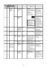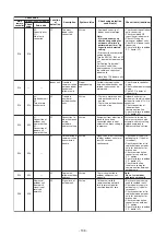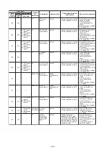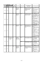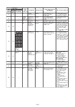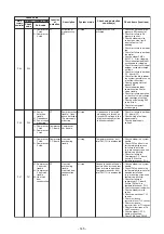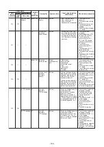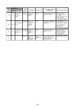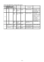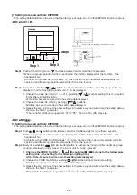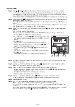
9-5. Diagnostic Procedure for Each Check Code (Indoor Unit)
Yes
Yes
No
Yes
Yes
Yes
No
Yes
No
No
No
No
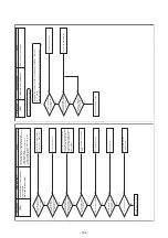
[E01]
Check code
Check code name
Cause
Communication trouble between
the indoor unit and remote
controller (detected on the remote
controller)
1. Remote controller inter-unit wire trouble
2. Indoor power trouble
3. Indoor P.C. board trouble
4. Remote controller address setup trouble
5. Remote controller P.C. board trouble
Is the
inter-unit wire of
remote controllers (A/B)
normal?
Is the
connector on the
harness or the harness
from terminal block of
indoor unit connected
correctly?
Is a group control
operation?
Is power of each indoor
unit turned on?
Is power applied
to remote controller?
AB terminals: Approx.
DC18V
Is one of two
remote controllers
set as a header unit?
Correct inter-unit cable of
remote controller.
Correct connector connection
and check circuit wiring.
Check power connection
status of indoor unit. (Turn on
power again.)
Replace indoor P.C. board.
Replace remote controller.
Change one to header/other to
follower. (Remote controller
address connector)
Check code
Check code name
Cause
Check code
Check code name
Cause
* The check code is not indicated on the central control device or the 7-segment indication on the outdoor unit.
Yes
No
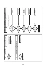
[E02]
[E03]
Signal transmission trouble on the
remote controller
Communication trouble between
the indoor unit and remote
controller controller
(detected on the indoor unit)
Unable to send signals to indoor units
No communication from the remote
controller/communication adapter
The
communication wiring
between the remote
controller and indoor units
is connected properly.
Connect the wiring properly.
The transmission circuit in the
remote controller malfunctions.
Replace the remote controller.
The trouble is detected when the indoor unit cannot receive the signal from the wired remote controller.
Check the communication wiring from the remote controller A and B.
The check code [E03] is not indicated on the remote controller as its communication is down.
However, the code is indicated on the
central controller.
- 151 -
Summary of Contents for MMC-UP0151HP-E
Page 41: ...2 2 Ceiling type MMC UP0151HP E TR MMC UP0181HP E TR 41 ...
Page 42: ...MMC UP0241HP E TR MMC UP0271HP E TR 6 4 12 7 42 ...
Page 43: ...MMC UP0361HP E TR MMC UP0481HP E TR MMC UP0561HP E TR 43 ...
Page 58: ...3 WIRING DIAGRAMS 3 1 4 way cassette type MMU UP HP E TR 58 ...
Page 59: ...3 2 Ceiling type MMC UP HP E TR 59 ...
Page 60: ...3 3 Concealed Duct Standard type MMD UP BHP E TR 60 ...
Page 61: ...3 4 Concealed Duct High Static Pressure type MMD UP HP E TR 61 ...
Page 62: ...Concealed Duct High Static Pressure type MMD UP HP E TR 62 ...
Page 63: ...3 5 Concealed Duct High Static Pressure fresh air intake type MMD UP HFP E TR 63 ...
Page 65: ...3 7 High wall type MMK UP HP E TR 65 ...
Page 249: ...MMU UP0361HP E TR MMU UP0481HP E TR MMU UP0561HP E TR 268 267 213 214 249 ...
Page 252: ...12 2 Ceiling type MMC UP0151HP E TR MMC UP0181HP E TR 025 024 252 ...
Page 254: ...MMC UP0241HP E TR MMC UP0271HP E TR 029 028 254 ...
Page 256: ...MMC UP0361HP E TR MMC UP0481HP E TR MMC UP0561HP E TR 051 028 027 256 ...
Page 261: ...MMD UP0151BHP E TR MMD UP0181BHP E TR 240 239 238 233 235 261 ...
Page 263: ...MMD UP0241BHP E TR MMD UP0271BHP E TR MMD UP0301BHP E TR 240 239 238 233 235 263 ...
Page 265: ...MMD UP0361BHP E TR MMD UP0481BHP E TR MMD UP0561BHP E TR 240 239 238 233 235 265 ...

