


51
1
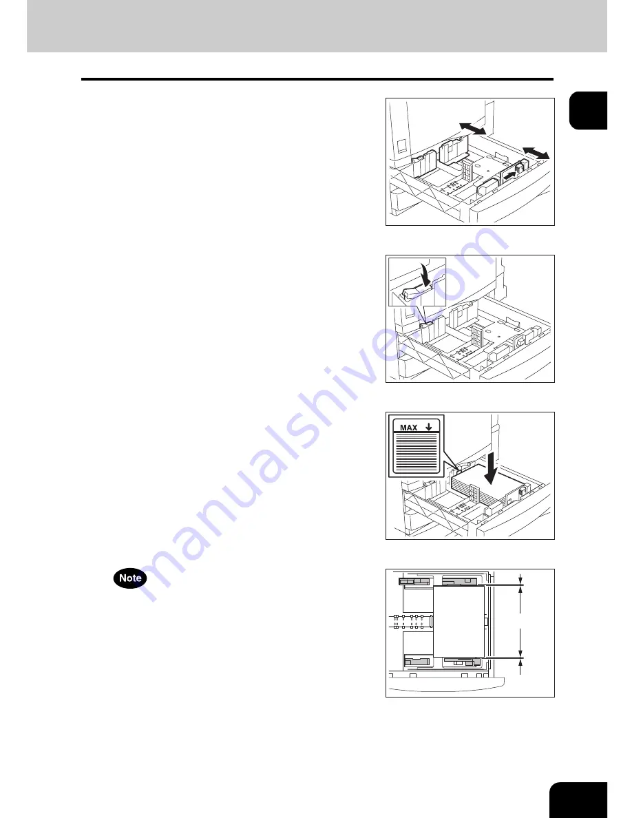
5
While pushing the green lever of the side
guide in the direction of the arrow, set
the side guide to the desired paper size.
• Adjust the side guides with both hands.
6
Push the arrow part (left side) to lock the
side guide.
7
Place paper in the drawer(s).
• Place paper with its copy side up. (The copy side may be
described on the wrapping paper.)
• For the maximum number of sheets that can be set, see
P.48
“Acceptable copy paper”.
• Fan the paper well before placing it in the drawer.
• Be sure that the paper height does not exceed the line indicated
inside of the guide.
• Do not use creased, folded, wrinkled or damp sheets of paper.
Make sure that a gap of 0.5 mm (1.0 mm or less in total) is left
between the paper and the side guide for plain paper, and approx.
0.5 mm to 1.0 mm (approx. 1.0 mm to 2.0 mm in total) for thick
paper. If the gap is insufficient, it could cause paper misfeeding.
A
Summary of Contents for E-STUDIO 232
Page 1: ...MULTIFUNCTIONAL DIGITAL SYSTEMS Operator s Manual for Basic Function ...
Page 2: ......
Page 6: ...4 CONTENTS Cont ...
Page 10: ...8 Toshiba Quality is Second to None Cont For e STUDIO233 283 ...
Page 24: ...22 Environmental Information Cont ...
Page 92: ...90 2 HOW TO MAKE COPIES 4 Proof Copy Cont 2 ...
Page 107: ...105 3 Names of each Inner Finisher optional 1 Trays 2 Paper stopper MJ 5004 MJ 5005 1 2 1 ...
Page 130: ...128 3 SETTING OF BASIC COPY MODES 6 Copy Density Adjustment Cont 3 ...
Page 131: ...129 4 4 IMAGE ADJUSTMENT 1 Background Adjustment 130 2 Sharpness 131 ...
Page 134: ...132 4 IMAGE ADJUSTMENT 2 Sharpness Cont 4 ...
Page 139: ...137 5 6 Press the ENTER button Select other copy modes as required 7 Press the START button ...
Page 175: ...173 5 5 Press the ENTER button Select other copy modes as required 6 Press the START button ...
Page 180: ...178 5 USING THE EDITING FUNCTIONS 16 ADF SADF Cont 5 ...
Page 206: ...204 6 e FILING 8 Appendix Cont 6 ...
Page 276: ...274 8 JOB STATUS 6 Error Code Cont 8 ...
Page 285: ...283 9 13Close the front cover ...
Page 304: ...302 9 BLINKING GRAPHIC SYMBOLS 5 Call Service Symbol Cont 9 ...
Page 328: ...326 10 WHEN THIS MESSAGE APPEARS 8 Reboot the machine Cont 10 ...
Page 329: ...327 11 11 MAINTENANCE 1 Daily Inspection 328 2 Simple Troubleshooting 330 ...
Page 336: ...334 11 MAINTENANCE 2 Simple Troubleshooting Cont 11 ...
Page 353: ...DP 2340 2840 OME050120E0 ...


