Reelmaster 7000
Page 3 -- 13
Kubota Diesel Engine
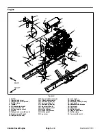
Engine Removal (Fig. 8)
1. Park machine on a level surface, lower cutting units,
stop engine, engage parking brake and remove key
from the ignition switch.
2. Remove hood from the machine (see Hood Removal
in the Service and Repairs section of Chapter 7 -- Chas-
sis).
3. Remove battery cover. Disconnect negative battery
cable first and then positive battery cable.
CAUTION
Do not open radiator cap or drain coolant if the
radiator or engine is hot. Pressurized, hot cool-
ant can escape and cause burns.
Ethylene--glycol antifreeze is poisonous. Dis-
pose of coolant properly, or store it in a properly
labeled container away from children and pets.
4. Drain coolant from radiator into a suitable container
(see Radiator Removal in this section). Disconnect cool-
ant hoses from the radiator.
CAUTION
The exhaust system may be hot. To avoid pos-
sible burns, allow the exhaust system to cool be-
fore working on or near the muffler.
5. Remove exhaust system from engine (see Exhaust
System Removal in this section).
6. Remove air cleaner system from engine (see Air
Cleaner Removal in this section).
7. Note location of cable ties used to secure wire har-
ness. Disconnect wire harness connectors from the fol-
lowing engine components:
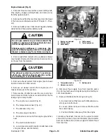
A. The engine run solenoid (Fig. 9).
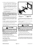
B. The temperature sender (Fig. 10).
C. The alternator (Fig. 10).
D. The glow plug connection.
E. Wire harness connector from engine ground har-
ness.
F. The electric starter motor.
G. Low oil pressure switch located on alternator side
of engine (above electric starter).
Figure 9
1. Engine run solenoid
2. Throttle cable
3. Cable clamp
4. Cable swivel
5. Fuel supply hose
2
1
3
4
5
Figure 10
1. Temperature sender
2. Harness connector
3. Battery cable
2
1
3
8. Disconnect fuel supply hose from injection pump
(Fig. 9). Cap fuel hose and injector pump fuel inlet to pre-
vent contamination.
9. Remove throttle cable from engine (Fig. 9):
A. Remove lock nut that secures throttle cable swiv-
el to speed control lever.
B. Loosen cable clamp and remove throttle cable
from under clamp.
C. Position throttle cable away from the engine.
10.Remove fasteners that secure the upper radiator
shroud to the lower shroud and radiator (see Radiator
Removal in this section). Remove upper radiator shroud
from machine.
Kubota
Diesel
Engine
Summary of Contents for Reelmaster 7000
Page 2: ...Reelmaster 7000 This page is intentionally blank ...
Page 4: ...Reelmaster 7000 This page is intentionally blank ...
Page 10: ...Reelmaster 7000 Page 1 6 Safety This page is intentionally blank ...
Page 12: ...0 09375 Reelmaster 7000 Page 2 2 Product Records and Maintenance Equivalents and Conversions ...
Page 34: ...Reelmaster 7000 Page 3 18 Kubota Diesel Engine This page is intentionally blank ...
Page 36: ...Reelmaster 7000 Hydraulic System Page 4 2 This page is intentionally blank ...
Page 45: ...Reelmaster 7000 Hydraulic System Page 4 11 This page is intentionally blank Hydraulic System ...
Page 115: ...Reelmaster 7000 Hydraulic System Page 4 81 This page is intentionally blank Hydraulic System ...
Page 131: ...Reelmaster 7000 Hydraulic System Page 4 97 This page is intentionally blank Hydraulic System ...
Page 139: ...Reelmaster 7000 Hydraulic System Page 4 105 This page is intentionally blank Hydraulic System ...
Page 147: ...Reelmaster 7000 Hydraulic System Page 4 113 This page is intentionally blank Hydraulic System ...
Page 151: ...Reelmaster 7000 Hydraulic System Page 4 117 This page is intentionally blank Hydraulic System ...
Page 168: ...Reelmaster 7000 Hydraulic System Page 4 134 This page is intentionally blank ...
Page 214: ...Reelmaster 7000 Page 5 46 Electrical System This page is intentionally blank ...
Page 247: ...Reelmaster 7000 Page 7 3 Chassis This page is intentionally blank Chassis ...
Page 264: ...Reelmaster 7000 Page 7 20 Chassis This page is intentionally blank ...
Page 271: ...Reelmaster 7000 DPA Cutting Units Page 8 7 This page is intentionally blank DPA Cutting Units ...
Page 304: ...Reelmaster 7000 DPA Cutting Units Page 8 40 This page is intentionally blank ...
Page 306: ...Reelmaster 7000 Foldout Drawings Page 9 2 This page is intentionally blank ...
Page 310: ...Page 9 6 Reelmaster 7000 Main Wire Harness ...
Page 312: ...Page 9 8 Reelmaster 7000 Seat and Console Wire Harness ...
Page 314: ...Page 9 10 Reelmaster 7000 Power Center Wire Harness ...

