Reelmaster 7000
Hydraulic System
Page 4 -- 53
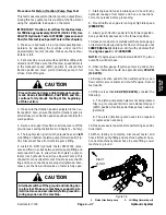
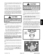
Procedure for Cutting Unit Motor Case Drain Leak-
age Test
NOTE:
Over a period of time, a cutting unit motor can
wear internally. A worn motor may bypass oil to its case
drain causing the motor to be less efficient. Eventually,
enough oil loss will cause the motor to stall under heavy
cutting conditions. Continued operation with a worn, in-
efficient motor can generate excessive heat, cause
damage to seals and other components in the hydraulic
system and affect quality of cut.
NOTE:
One method to find a failing or malfunctioning
cutting unit motor is to have another person observe the
machine while mowing in dense turf. A bad motor will run
slower, produce fewer clippings and may cause a differ-
ent appearance on the turf.
1. Make sure hydraulic oil is at normal operating tem-
perature by operating the machine for approximately ten
(10) minutes. Make sure the hydraulic tank is full.
2. Park machine on a level surface with the cutting units
lowered and off. Make sure engine is off and the parking
brake is engaged.
CAUTION
Prevent personal injury and/or damage to equip-
ment. Read all WARNINGS, CAUTIONS and Pre-
cautions for Hydraulic Testing at the beginning
of this section.
NOTE:
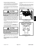
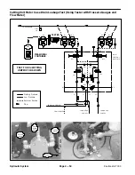
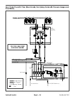
The cutting unit motors are connected in series.
To isolate a faulty motor, all motors in the circuit may
have to be tested by starting with the first motor in the
circuit (see Hydraulic Schematic).
IMPORTANT: Make sure that the oil flow indicator
arrow on the tester is showing that the oil will flow
from the motor fitting, through the tester and into
the disconnected hose.
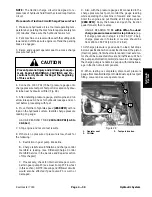
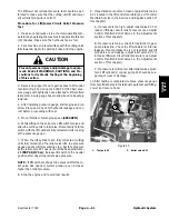
3. Disconnect hydraulic return hose (rear hose) from
the motor to be tested. Install tester with pressure gauge
and flow meter in series with the motor and the discon-
nected return hose. Make sure the flow control valve on
tester is fully open.
4. Disconnect the motor case drain hose (small diame-
ter hose) where it connects to bulkhead fitting at the
frame rail (not at the motor). Put a steel cap on the bulk-
head fitting; leave the case drain hose open.
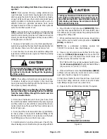
5. Start engine and run at low idle speed. Check for hy-
draulic leakage and correct before proceeding with test.
CAUTION
Cutting reel blades will rotate when lowered with
PTO switch in ON position. Keep away from cut-
ting units during test to prevent personal injury
from rotating reel blades. Do not stand in front of
the machine during test.
6. Move throttle to high idle speed
(2850 RPM)
. Make
sure that mow speed limiter is in the mow (4WD) posi-
tion. With seat occupied, release the parking brake and
engage the cutting units.
7. While watching tester pressure gauge, slowly close
flow control valve on tester until a pressure of
1200 PSI
(83 bar)
is obtained.
NOTE:
Use a graduated container, special tool
TOR4077, to measure case drain leakage.
8. Have a second person measure flow from the case
drain line for
fifteen (15) seconds
, then move the PTO
switch to OFF, open the tester flow control valve and
stop the engine. Record test results.
TEST RESULTS: Case drain leakage should be less
than
22.4 ounces (662 ml)
of hydraulic fluid in fifteen
(15) seconds (0.7 GPM / 2.7 LPM).
9. If case drain flow is more than
22.4 ounces (662 ml)
in fifteen (15) seconds, the reel motor is worn or dam-
aged and should be repaired or replaced.
10.Disconnect tester from motor and hose. Reconnect
hose to the cutting unit motor. Remove cap from bulk-
head fitting and reconnect case drain hose.
11.Repeat test for additional reel motors if required.
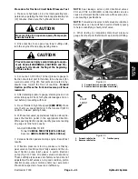
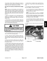
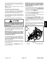
Figure 41
CUTTING UNIT LOCATIONS
#4
#1
#5
#3
#2
Hydraulic System
Summary of Contents for Reelmaster 7000
Page 2: ...Reelmaster 7000 This page is intentionally blank ...
Page 4: ...Reelmaster 7000 This page is intentionally blank ...
Page 10: ...Reelmaster 7000 Page 1 6 Safety This page is intentionally blank ...
Page 12: ...0 09375 Reelmaster 7000 Page 2 2 Product Records and Maintenance Equivalents and Conversions ...
Page 34: ...Reelmaster 7000 Page 3 18 Kubota Diesel Engine This page is intentionally blank ...
Page 36: ...Reelmaster 7000 Hydraulic System Page 4 2 This page is intentionally blank ...
Page 45: ...Reelmaster 7000 Hydraulic System Page 4 11 This page is intentionally blank Hydraulic System ...
Page 115: ...Reelmaster 7000 Hydraulic System Page 4 81 This page is intentionally blank Hydraulic System ...
Page 131: ...Reelmaster 7000 Hydraulic System Page 4 97 This page is intentionally blank Hydraulic System ...
Page 139: ...Reelmaster 7000 Hydraulic System Page 4 105 This page is intentionally blank Hydraulic System ...
Page 147: ...Reelmaster 7000 Hydraulic System Page 4 113 This page is intentionally blank Hydraulic System ...
Page 151: ...Reelmaster 7000 Hydraulic System Page 4 117 This page is intentionally blank Hydraulic System ...
Page 168: ...Reelmaster 7000 Hydraulic System Page 4 134 This page is intentionally blank ...
Page 214: ...Reelmaster 7000 Page 5 46 Electrical System This page is intentionally blank ...
Page 247: ...Reelmaster 7000 Page 7 3 Chassis This page is intentionally blank Chassis ...
Page 264: ...Reelmaster 7000 Page 7 20 Chassis This page is intentionally blank ...
Page 271: ...Reelmaster 7000 DPA Cutting Units Page 8 7 This page is intentionally blank DPA Cutting Units ...
Page 304: ...Reelmaster 7000 DPA Cutting Units Page 8 40 This page is intentionally blank ...
Page 306: ...Reelmaster 7000 Foldout Drawings Page 9 2 This page is intentionally blank ...
Page 310: ...Page 9 6 Reelmaster 7000 Main Wire Harness ...
Page 312: ...Page 9 8 Reelmaster 7000 Seat and Console Wire Harness ...
Page 314: ...Page 9 10 Reelmaster 7000 Power Center Wire Harness ...

