Reelmaster 7000
Page 5 -- 20
Electrical System
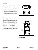
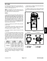
Hour Meter
The hour meter is located on the outside of the console
arm.
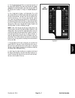
1. Connect the positive (+) terminal of a 12 VDC source
to the positive (+) terminal of the hour meter.
2. Connect the negative (--) terminal of the voltage
source to the other terminal of the hour meter.
3. The hour meter should move a 1/10 of an hour in six
(6) minutes.
4. Disconnect voltage source from the hour meter.
Figure 21
QUARTZ
Hobbs
HOURS
1
0 0 0 0
1
10
+
BACK
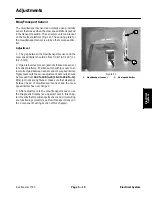
Temperature Gauge
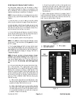
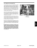
The temperature gauge on the control panel indicates
engine coolant temperature level during machine op-
eration (Fig. 22). The changing resistance of the engine
temperature sender signals the temperature gauge.
The temperature gauge should display the first green
segment when the ignition switch is turned to ON. The
first yellow segment on the gauge should display when
engine coolant temperature is approximately 212
o
F
(100
o
C).
When engine coolant temperature rises to approximate-
ly 221
o
F (105
o
C), the temperature gauge should display
the first red segment.
1. Console arm
2. Temperature gauge
3. High temp indicator
Figure 22
1
2
3
Summary of Contents for Reelmaster 7000
Page 2: ...Reelmaster 7000 This page is intentionally blank ...
Page 4: ...Reelmaster 7000 This page is intentionally blank ...
Page 10: ...Reelmaster 7000 Page 1 6 Safety This page is intentionally blank ...
Page 12: ...0 09375 Reelmaster 7000 Page 2 2 Product Records and Maintenance Equivalents and Conversions ...
Page 34: ...Reelmaster 7000 Page 3 18 Kubota Diesel Engine This page is intentionally blank ...
Page 36: ...Reelmaster 7000 Hydraulic System Page 4 2 This page is intentionally blank ...
Page 45: ...Reelmaster 7000 Hydraulic System Page 4 11 This page is intentionally blank Hydraulic System ...
Page 115: ...Reelmaster 7000 Hydraulic System Page 4 81 This page is intentionally blank Hydraulic System ...
Page 131: ...Reelmaster 7000 Hydraulic System Page 4 97 This page is intentionally blank Hydraulic System ...
Page 139: ...Reelmaster 7000 Hydraulic System Page 4 105 This page is intentionally blank Hydraulic System ...
Page 147: ...Reelmaster 7000 Hydraulic System Page 4 113 This page is intentionally blank Hydraulic System ...
Page 151: ...Reelmaster 7000 Hydraulic System Page 4 117 This page is intentionally blank Hydraulic System ...
Page 168: ...Reelmaster 7000 Hydraulic System Page 4 134 This page is intentionally blank ...
Page 214: ...Reelmaster 7000 Page 5 46 Electrical System This page is intentionally blank ...
Page 247: ...Reelmaster 7000 Page 7 3 Chassis This page is intentionally blank Chassis ...
Page 264: ...Reelmaster 7000 Page 7 20 Chassis This page is intentionally blank ...
Page 271: ...Reelmaster 7000 DPA Cutting Units Page 8 7 This page is intentionally blank DPA Cutting Units ...
Page 304: ...Reelmaster 7000 DPA Cutting Units Page 8 40 This page is intentionally blank ...
Page 306: ...Reelmaster 7000 Foldout Drawings Page 9 2 This page is intentionally blank ...
Page 310: ...Page 9 6 Reelmaster 7000 Main Wire Harness ...
Page 312: ...Page 9 8 Reelmaster 7000 Seat and Console Wire Harness ...
Page 314: ...Page 9 10 Reelmaster 7000 Power Center Wire Harness ...


