Reelmaster 7000
Page 5 -- 25
Electrical System
Seat Switch
The seat switch is normally open and closes when the
operator is on the seat. The seat switch and its electrical
connector are located in the seat assembly. If the trac-
tion system or PTO switch is engaged when the operator
raises out of the seat, the engine will stop. Testing of the
switch can be done without seat removal by disconnect-
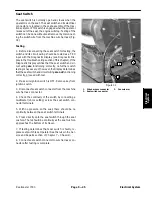
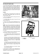
ing the switch wire from the machine wire harness (Fig.
32).
Testing
1. Before disconnecting the seat switch for testing, the
switch and its circuit wiring should be tested as a TEC
input with the Diagnostic Display (see Diagnostic Dis-
play in the Troubleshooting section of this chapter). If the
Diagnostic Display verifies that the seat switch and cir-
cuit wiring
are
functioning correctly, no further switch
testing is necessary. If, however, the Display determines
that the seat switch and circuit wiring
are not
functioning
correctly, proceed with test.
2. Make sure ignition switch is OFF. Remove key from
ignition switch.
3. Disconnect seat switch connector from the machine
wire harness connector.
4. Check the continuity of the switch by connecting a
multimeter (ohms setting) across the seat switch con-
nector terminals.
5. With no pressure on the seat, there should be no
continuity between the seat switch terminals.
6. Press directly onto the seat switch through the seat
cushion. There should be continuity as the seat cushion
approaches the bottom of its travel.
7. If testing determines that seat switch is faulty, re-
place seat switch (see Operator Seat Service in the Ser-
vice and Repairs section of Chapter 7 -- Chassis).
8. Connect seat switch connector to wire harness con-
nector after testing is complete.
1. Wire harness connector
2. Seat switch connector
3. Console arm
Figure 32
2
1
3
Electrical System
Summary of Contents for Reelmaster 7000
Page 2: ...Reelmaster 7000 This page is intentionally blank ...
Page 4: ...Reelmaster 7000 This page is intentionally blank ...
Page 10: ...Reelmaster 7000 Page 1 6 Safety This page is intentionally blank ...
Page 12: ...0 09375 Reelmaster 7000 Page 2 2 Product Records and Maintenance Equivalents and Conversions ...
Page 34: ...Reelmaster 7000 Page 3 18 Kubota Diesel Engine This page is intentionally blank ...
Page 36: ...Reelmaster 7000 Hydraulic System Page 4 2 This page is intentionally blank ...
Page 45: ...Reelmaster 7000 Hydraulic System Page 4 11 This page is intentionally blank Hydraulic System ...
Page 115: ...Reelmaster 7000 Hydraulic System Page 4 81 This page is intentionally blank Hydraulic System ...
Page 131: ...Reelmaster 7000 Hydraulic System Page 4 97 This page is intentionally blank Hydraulic System ...
Page 139: ...Reelmaster 7000 Hydraulic System Page 4 105 This page is intentionally blank Hydraulic System ...
Page 147: ...Reelmaster 7000 Hydraulic System Page 4 113 This page is intentionally blank Hydraulic System ...
Page 151: ...Reelmaster 7000 Hydraulic System Page 4 117 This page is intentionally blank Hydraulic System ...
Page 168: ...Reelmaster 7000 Hydraulic System Page 4 134 This page is intentionally blank ...
Page 214: ...Reelmaster 7000 Page 5 46 Electrical System This page is intentionally blank ...
Page 247: ...Reelmaster 7000 Page 7 3 Chassis This page is intentionally blank Chassis ...
Page 264: ...Reelmaster 7000 Page 7 20 Chassis This page is intentionally blank ...
Page 271: ...Reelmaster 7000 DPA Cutting Units Page 8 7 This page is intentionally blank DPA Cutting Units ...
Page 304: ...Reelmaster 7000 DPA Cutting Units Page 8 40 This page is intentionally blank ...
Page 306: ...Reelmaster 7000 Foldout Drawings Page 9 2 This page is intentionally blank ...
Page 310: ...Page 9 6 Reelmaster 7000 Main Wire Harness ...
Page 312: ...Page 9 8 Reelmaster 7000 Seat and Console Wire Harness ...
Page 314: ...Page 9 10 Reelmaster 7000 Power Center Wire Harness ...

