Reelmaster 7000
Page 5 -- 37
Electrical System
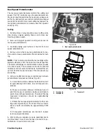
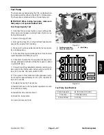
Fuel Pump
The fuel pump is energized by the TEC controller when
the ignition switch is either in the START or ON position.
The fuel pump is attached to the left side frame rail.
IMPORTANT: When testing fuel pump, make sure
that pump is not operated without fuel.
Fuel Pump Capacity Test
1. Park machine on a level surface, lower cutting units,
stop engine and engage parking brake. Remove key
from ignition switch.
2. Raise and support hood.
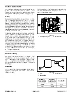
3. Remove 20A fuse (F1--1) (Fig. 54) from fuse block to
prevent the engine from cranking.
4. Make sure fuel hoses attached to the fuel pump are
free of obstructions.
5. Disconnect fuel pump discharge hose from the fuel/
water separator inlet fitting (Fig. 53).
6. Place disconnected fuel hose (pump discharge) into
a large, graduated cylinder sufficient enough to collect
1 quart (0.95 liter).
7. Collect fuel in the graduated cylinder by turning igni-
tion switch to the ON position. Allow pump to run for fif-
teen (15) seconds, then turn switch to OFF.
8. The amount of fuel collected in the graduated cylin-
der should be approximately 16 fl oz (475 ml) after fif-
teen (15) seconds.
9. Replace fuel pump if necessary.
10.Install fuel hose to the fuel/water separator. Secure
hose with hose clamp.
11.Install 20A fuse into fuse block.
12.Bleed the fuel system.
13.Lower and secure hood.
1. Fuel/water separator
2. Pump discharge hose
3. Inlet fitting
Figure 53
2
1
3
Figure 54
FRONT
F3
F2
F1
2A
7.5A
7.5A
7.5A
10A
10A
10A
10A
20A
OP
TION
OP
TION
OP
TION
M1 (60A)
M2 (option)
Fuel Pump Specifications
Pump Capacity
64 fl oz/min (1.9 l/min)
Pressure
7 PSI (48.3 kPa)
Current Draw
2.0 amp
Electrical System
Summary of Contents for Reelmaster 7000
Page 2: ...Reelmaster 7000 This page is intentionally blank ...
Page 4: ...Reelmaster 7000 This page is intentionally blank ...
Page 10: ...Reelmaster 7000 Page 1 6 Safety This page is intentionally blank ...
Page 12: ...0 09375 Reelmaster 7000 Page 2 2 Product Records and Maintenance Equivalents and Conversions ...
Page 34: ...Reelmaster 7000 Page 3 18 Kubota Diesel Engine This page is intentionally blank ...
Page 36: ...Reelmaster 7000 Hydraulic System Page 4 2 This page is intentionally blank ...
Page 45: ...Reelmaster 7000 Hydraulic System Page 4 11 This page is intentionally blank Hydraulic System ...
Page 115: ...Reelmaster 7000 Hydraulic System Page 4 81 This page is intentionally blank Hydraulic System ...
Page 131: ...Reelmaster 7000 Hydraulic System Page 4 97 This page is intentionally blank Hydraulic System ...
Page 139: ...Reelmaster 7000 Hydraulic System Page 4 105 This page is intentionally blank Hydraulic System ...
Page 147: ...Reelmaster 7000 Hydraulic System Page 4 113 This page is intentionally blank Hydraulic System ...
Page 151: ...Reelmaster 7000 Hydraulic System Page 4 117 This page is intentionally blank Hydraulic System ...
Page 168: ...Reelmaster 7000 Hydraulic System Page 4 134 This page is intentionally blank ...
Page 214: ...Reelmaster 7000 Page 5 46 Electrical System This page is intentionally blank ...
Page 247: ...Reelmaster 7000 Page 7 3 Chassis This page is intentionally blank Chassis ...
Page 264: ...Reelmaster 7000 Page 7 20 Chassis This page is intentionally blank ...
Page 271: ...Reelmaster 7000 DPA Cutting Units Page 8 7 This page is intentionally blank DPA Cutting Units ...
Page 304: ...Reelmaster 7000 DPA Cutting Units Page 8 40 This page is intentionally blank ...
Page 306: ...Reelmaster 7000 Foldout Drawings Page 9 2 This page is intentionally blank ...
Page 310: ...Page 9 6 Reelmaster 7000 Main Wire Harness ...
Page 312: ...Page 9 8 Reelmaster 7000 Seat and Console Wire Harness ...
Page 314: ...Page 9 10 Reelmaster 7000 Power Center Wire Harness ...

