Reelmaster 7000
Hydraulic System
Page 4 -- 63
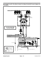
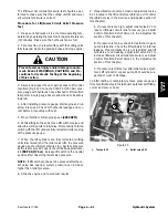
The gear pump P3 flow test should be performed to
make sure that the steering, lift and traction charge cir-
cuits have adequate hydraulic flow.
NOTE:
Gear Pump P3 supplies oil flow for the steering,
lift and traction charge circuits.
Procedure for Gear Pump P3 Flow Test
1. Make sure hydraulic oil is at normal operating tem-
perature by operating the machine for approximately ten
(10) minutes. Make sure the hydraulic tank is full.
2. Park machine on a level surface with the cutting units
lowered and off. Make sure engine is off and the parking
brake is engaged.
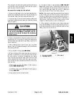
3. Raise hood to allow access to pump assembly.
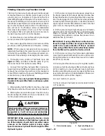
CAUTION
Prevent personal injury and/or damage to equip-
ment. Read all WARNINGS, CAUTIONS and Pre-
cautions for Hydraulic Testing at the beginning
of this section.
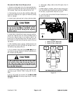
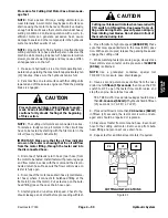
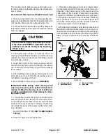
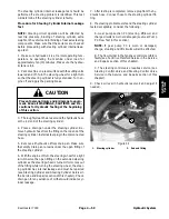
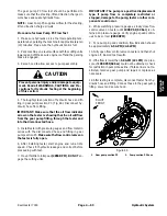
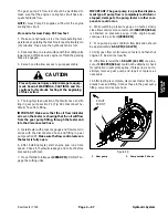
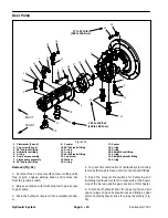
4. Thoroughly clean junction of hydraulic hose and fit-
ting in gear pump section P3 (Fig. 46). Disconnect hy-
draulic hose from fitting.
IMPORTANT: Make sure that the oil flow indicator
arrow on the tester is showing that the oil will flow
from the gear pump fitting, through the tester and
into the disconnected hose.
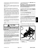
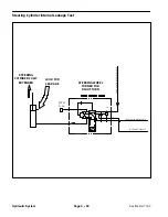
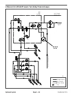
5. Install tester with pressure gauges and flow meter in
series with the disconnected hose and fitting in gear
pump section P3.
Make sure the flow control valve on
the tester is fully open.
6. After installing tester, start engine and run at idle
speed. Check for hydraulic leakage and correct before
proceeding with test.
7. Move throttle to full speed
(2850 RPM)
.
DO NOT
en-
gage the cutting units.
IMPORTANT: The pump is a positive displacement
type. If pump flow is completely restricted or
stopped, damage to the pump, tester or other com-
ponents could occur.
8. While watching pressure gauges, slowly close flow
control valve on tester until
1000 PSI (69 bar)
is ob-
tained on pressure gauge. Verify engine speed contin-
ues to be correct
(2850 RPM)
.
9. For a pump in good condition, flow indication should
be approximately
6.5 GPM (24.6 LPM)
.
10.Fully open flow control valve on tester and then shut
engine off. Record test results.
11.If the flow is lower than
5.8 GPM (22 LPM)
or a pres-
sure of
1000 PSI (69 bar)
could not be obtained, check
for restriction in pump intake line. If intake line is not re-
stricted, remove gear pump and repair or replace as
necessary.
12.After testing is complete, disconnect tester from hy-
draulic hose and fitting. Connect hose to the gear pump
fitting. Lower and secure hood.
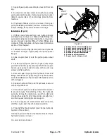
1. Gear pump section P3
2. Pump section P3 hose
Figure 46
FRONT
RIGHT
1
2
Hydraulic System
Summary of Contents for Reelmaster 7000
Page 2: ...Reelmaster 7000 This page is intentionally blank ...
Page 4: ...Reelmaster 7000 This page is intentionally blank ...
Page 10: ...Reelmaster 7000 Page 1 6 Safety This page is intentionally blank ...
Page 12: ...0 09375 Reelmaster 7000 Page 2 2 Product Records and Maintenance Equivalents and Conversions ...
Page 34: ...Reelmaster 7000 Page 3 18 Kubota Diesel Engine This page is intentionally blank ...
Page 36: ...Reelmaster 7000 Hydraulic System Page 4 2 This page is intentionally blank ...
Page 45: ...Reelmaster 7000 Hydraulic System Page 4 11 This page is intentionally blank Hydraulic System ...
Page 115: ...Reelmaster 7000 Hydraulic System Page 4 81 This page is intentionally blank Hydraulic System ...
Page 131: ...Reelmaster 7000 Hydraulic System Page 4 97 This page is intentionally blank Hydraulic System ...
Page 139: ...Reelmaster 7000 Hydraulic System Page 4 105 This page is intentionally blank Hydraulic System ...
Page 147: ...Reelmaster 7000 Hydraulic System Page 4 113 This page is intentionally blank Hydraulic System ...
Page 151: ...Reelmaster 7000 Hydraulic System Page 4 117 This page is intentionally blank Hydraulic System ...
Page 168: ...Reelmaster 7000 Hydraulic System Page 4 134 This page is intentionally blank ...
Page 214: ...Reelmaster 7000 Page 5 46 Electrical System This page is intentionally blank ...
Page 247: ...Reelmaster 7000 Page 7 3 Chassis This page is intentionally blank Chassis ...
Page 264: ...Reelmaster 7000 Page 7 20 Chassis This page is intentionally blank ...
Page 271: ...Reelmaster 7000 DPA Cutting Units Page 8 7 This page is intentionally blank DPA Cutting Units ...
Page 304: ...Reelmaster 7000 DPA Cutting Units Page 8 40 This page is intentionally blank ...
Page 306: ...Reelmaster 7000 Foldout Drawings Page 9 2 This page is intentionally blank ...
Page 310: ...Page 9 6 Reelmaster 7000 Main Wire Harness ...
Page 312: ...Page 9 8 Reelmaster 7000 Seat and Console Wire Harness ...
Page 314: ...Page 9 10 Reelmaster 7000 Power Center Wire Harness ...

