Reelmaster 7000
Page 5 -- 15
Electrical System
Adjustments
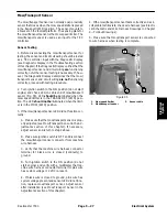
Mow/Transport Sensor
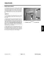
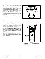
The mow/transport sensor is a normally open proximity
sensor that closes when the mow speed limiter is placed
in the transport position. The sensor mounts to a bracket
on the footrest platform (Fig. 12). The sensing plate for
the mow/transport sensor is a tab on the mow speed lim-
iter.
Adjustment
1. The gap between the mow/transport sensor and the
mow speed limiter should be from 0.040” to 0.100” (1.1
to 2.5 mm).
2. If gap is incorrect, loosen jam nuts that secure sensor
to footrest platform. Position switch with jam nuts to al-
low correct gap between sensor and mow speed limiter.
Tighten jam nuts to secure adjustment. Jam nuts should
be torqued from
162 to 198 in--lb (18.4 to 22.4 N--m)
.
After jam nuts are tightened, make sure that clearance
between head of mow/transport sensor and the mow
speed limiter has not changed.
3. After adjustment to the mow/transport sensor, use
the Diagnostic Display (see Special Tools in this chap-
ter) to verify that mow/transport sensor and circuit wiring
are functioning correctly (see Mow/Transport Sensor in
the Component Testing section of this chapter).
1. Mow/transport sensor
2. Mow speed limiter
Figure 12
1
2
Electrical System
Summary of Contents for Reelmaster 7000
Page 2: ...Reelmaster 7000 This page is intentionally blank ...
Page 4: ...Reelmaster 7000 This page is intentionally blank ...
Page 10: ...Reelmaster 7000 Page 1 6 Safety This page is intentionally blank ...
Page 12: ...0 09375 Reelmaster 7000 Page 2 2 Product Records and Maintenance Equivalents and Conversions ...
Page 34: ...Reelmaster 7000 Page 3 18 Kubota Diesel Engine This page is intentionally blank ...
Page 36: ...Reelmaster 7000 Hydraulic System Page 4 2 This page is intentionally blank ...
Page 45: ...Reelmaster 7000 Hydraulic System Page 4 11 This page is intentionally blank Hydraulic System ...
Page 115: ...Reelmaster 7000 Hydraulic System Page 4 81 This page is intentionally blank Hydraulic System ...
Page 131: ...Reelmaster 7000 Hydraulic System Page 4 97 This page is intentionally blank Hydraulic System ...
Page 139: ...Reelmaster 7000 Hydraulic System Page 4 105 This page is intentionally blank Hydraulic System ...
Page 147: ...Reelmaster 7000 Hydraulic System Page 4 113 This page is intentionally blank Hydraulic System ...
Page 151: ...Reelmaster 7000 Hydraulic System Page 4 117 This page is intentionally blank Hydraulic System ...
Page 168: ...Reelmaster 7000 Hydraulic System Page 4 134 This page is intentionally blank ...
Page 214: ...Reelmaster 7000 Page 5 46 Electrical System This page is intentionally blank ...
Page 247: ...Reelmaster 7000 Page 7 3 Chassis This page is intentionally blank Chassis ...
Page 264: ...Reelmaster 7000 Page 7 20 Chassis This page is intentionally blank ...
Page 271: ...Reelmaster 7000 DPA Cutting Units Page 8 7 This page is intentionally blank DPA Cutting Units ...
Page 304: ...Reelmaster 7000 DPA Cutting Units Page 8 40 This page is intentionally blank ...
Page 306: ...Reelmaster 7000 Foldout Drawings Page 9 2 This page is intentionally blank ...
Page 310: ...Page 9 6 Reelmaster 7000 Main Wire Harness ...
Page 312: ...Page 9 8 Reelmaster 7000 Seat and Console Wire Harness ...
Page 314: ...Page 9 10 Reelmaster 7000 Power Center Wire Harness ...

