41
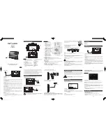
D2/D4 Heater Duct Installation (continued)
Discharge Air
1.
Find an appropriate location for the floor level
discharge air vent
and drill a
2-1/2”
hole using the correct
hole saw.
a.
Unsnap rotating outer louver assembly from the mounting base.
b.
Install the base into 2-1/2” hole and secure with supplied screws.
c.
Reinstall rotating outer louver assembly back into the mounting base ring. Verify that it rotates freely.
2.
Attach one end of the heater duct to the discharge outlet hood on the heater and secure with supplied clamp.
3.
Route the heater duct to the floor level discharge air vent, cut as needed, attach to the end of the plastic louver
vent and secure with supplied hose clamp.
Return Air
4.
If a return air duct is not used, the protective grille must be installed onto the heater inlet.
5.
Find an appropriate location for the floor level
return air grille
and drill a
2-1/2”
hole using the correct hole
saw.
a.
Install the return air grille into the 2-1/2” hole and secure with supplied screws.
6.
Attach one end of the return air duct to the air inlet hood on the heater and secure with supplied clamp.
a.
Route the return air duct to the return air grille, cut as needed, attach to the end of the plastic
louver vent and secure with supplied hose clamp.
Figure 20: Discharge and Return Air Duct Installation
Summary of Contents for TriPac Envidia
Page 2: ......
Page 11: ...9 Battery Box Dimensions Figure 1 Battery Box Dimensions...
Page 12: ...10 Battery Box Dimensions continued Figure 2 Battery Box Dimensions continued...
Page 13: ...11 Evaporator Control Box Dimensions Figure 3 Evaporator Control Box Dimensions...
Page 14: ...12 Condenser with Receiver Drier Dimensions Figure 4 Condenser with Receiver Drier Dimensions...
Page 15: ...13 HMI Dimensions Figure 5 HMI Dimensions...
Page 16: ...14 1000 Watt Power Inverter Dimensions Option Figure 6 1000 Watt Power Inverter Dimensions...
Page 18: ...16 D2 D4 Heater Dimensions Option Figure 8 Heater Dimension...
Page 19: ...17 BLANK PAGE...
Page 21: ...19 Typical Component Locations Figure 9 Typical Component Locations...
Page 45: ...43 A C Duct Installation continued FLUSH MOUNTED EVAPORATOR Figure 21 A C Duct locations...
Page 76: ......
Page 77: ......
Page 78: ......
Page 79: ......