38
D2/D4 Heater Installation (continued)
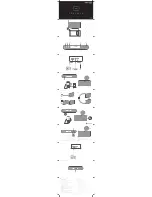
Heater Subassembly
Turn the heater upside down and attach the following components:
1.
Snap the air outlet hood onto the end of the heater.
2.
Place the mounting plate onto the heater studs. Mounting hardware will be installed later.
3.
Attach the short rubber hose and clamps onto the fuel inlet connection located at the base of the heater.
4.
Insert the plastic fuel line all the way into the rubber hose until it bottoms out to prevent air gaps. Tighten both
hose clamps securely.
5.
Attach the
exhaust hose
and
metal clamp
onto the fitting located under the
OUTLET
end of the heater. Turn
metal clamp to the center and tighten securely.
6.
Insert the plastic
air intake
tube through the beveled opening of the small plastic mounting plate. Install the
plastic plate and tube onto studs located under the
INLET
end of the heater.
7.
Install lock washers and nuts onto each of the mounting studs and tighten hardware securely.
8.
Install gasket to mounting plate.
9.
The heater has two service data nameplates. Remove one and reinstall it onto the top of the heater so that it is
visible when the heater is installed.
Heater Installation
10.
Position the heater over the access hole with intake and exhaust hose and fuel line exiting the tractor. Attach
the heater to the floor with TEK screws and tighten securely.
NOTE: Tighten TEK screws sufficiently to ensure a positive seal between mounting plate and mounting surface. Do
not over tighten!
Figure 18: Heater Subassembly and Installation.
Summary of Contents for TriPac Envidia
Page 2: ......
Page 11: ...9 Battery Box Dimensions Figure 1 Battery Box Dimensions...
Page 12: ...10 Battery Box Dimensions continued Figure 2 Battery Box Dimensions continued...
Page 13: ...11 Evaporator Control Box Dimensions Figure 3 Evaporator Control Box Dimensions...
Page 14: ...12 Condenser with Receiver Drier Dimensions Figure 4 Condenser with Receiver Drier Dimensions...
Page 15: ...13 HMI Dimensions Figure 5 HMI Dimensions...
Page 16: ...14 1000 Watt Power Inverter Dimensions Option Figure 6 1000 Watt Power Inverter Dimensions...
Page 18: ...16 D2 D4 Heater Dimensions Option Figure 8 Heater Dimension...
Page 19: ...17 BLANK PAGE...
Page 21: ...19 Typical Component Locations Figure 9 Typical Component Locations...
Page 45: ...43 A C Duct Installation continued FLUSH MOUNTED EVAPORATOR Figure 21 A C Duct locations...
Page 76: ......
Page 77: ......
Page 78: ......
Page 79: ......