B-1
APPENDIX B
RS-232/485 COMMANDS
RS-232/485 COMMANDS
The RS-232/485 interface enables the analyzer to be remotely controlled by a host remote
device such as, a PC, PLC, datalogger, etc. On the rear panel of the analyzer there are
two male DB9 connectors. Both connectors are identical, so either can be connected to
the remote device. The remaining connector can be used to connect a second analyzer.
Using a daisy-chain configuration, several analyzers can be connected to one remote
device.
RS-232 CONNECTION
A null modem (crossed) cable is required when connecting the analyzer to an IBM
Compatible PC. However, a straight cable (one to one) may be required when connecting the
analyzer to other host remote devices. As a general rule, when the connector of the host
remote device is female, a straight cable is required and when the connector is male, a null
modem cable is required.
DATA FORMAT
1200, 2400, 4800, or 9600 BAUD
8 data bits
1 stop bit
no
parity
All responses are terminated with a carriage return (hex 0D)
RS-485 CONNECTION
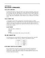
The instrument uses a four wire RS-485 configuration with automatic flow control (SD).
The pin configuration for DB9 connector on the rear of the instrument follows:
Pin# (DB9)
Function
4 +
receive
8 -
receive
2 +
transmit
7 -
transmit
5 ground
INSTRUMENT IDENTIFICATION NUMBER
Each command sent to the analyzer must begin with the instrument's identification
number plus 128. For example, if the instrument ID is set to 25, then decimal 153
precedes each command. The analyzer ignores any command that does no begin with its
instrument identification number.
Summary of Contents for 48C
Page 4: ......
Page 12: ......
Page 14: ......
Page 18: ......
Page 27: ...Chapter 3 Operation 3 3 Figure 3 2 Flowchart of Menu Driven Software ...
Page 112: ......
Page 116: ......
Page 120: ......
Page 123: ...Chapter 7 Servicing 7 3 Figure 7 2 Model 48C Component Layout 48P737 ...
Page 125: ...Chapter 7 Servicing 7 5 Figure 7 3 Optical Bench Exploded View 42P761 ...
Page 138: ......
Page 146: ...Chapter 9 Optional Equipment 9 2 Figure 9 2 Model 48C Dimensional Outline D42P725 ...
Page 155: ...Chapter 9 Optional Equipment Figure 9 8 Purge Housing Assembly 9 11 ...
Page 158: ......
Page 178: ...Appendix B RS 232 Commands B 20 µ ...
Page 184: ......
Page 186: ...C 2 ...
Page 187: ...C 3 ...
Page 188: ...C 4 ...
Page 189: ...C 5 ...
Page 190: ...C 6 ...
Page 191: ...C 7 ...
Page 192: ...C 8 ...
Page 193: ...C 9 ...
Page 194: ...C 10 ...
Page 195: ...C 11 ...
Page 196: ...C 12 ...
Page 197: ...C 13 ...
Page 198: ...C 14 ...
Page 199: ...C 15 ...
Page 200: ......
Page 201: ...APPENDIX D PUMP MAINTENANCE ...
Page 202: ......
Page 203: ......
Page 204: ......


