Chapter 4 Calibration
4-6
Additional Concentration Standards
Generate several additional concentrations (at least five others are suggested) by
decreasing F
CO
or increasing F
D
. Be sure the total flow exceeds the Model 48C's total
flow demand. For each concentration generated, calculate the exact CO concentration
using Equation (1). Record the concentration and the Model 48C's response for each
concentration.
Calibration Curve
Plot the Model 48C's response versus the corresponding CO concentrations. Connect the
experimental points using a straight line, preferably determined by linear regression
techniques. The calibration curve is used to reduce subsequent ambient data.
Frequency of Calibration
In order to generate data of the highest confidence, it is recommended that a multipoint
calibration be performed: every three months, any time any major disassembly of
components is performed, or any time the zero or span checks give results outside the
limits described in “Periodic Zero and Span Checks” below.
PERIODIC ZERO AND SPAN CHECKS
In order to achieve data of the highest confidence, it is suggest that periodic zero and air
span checks be performed. These checks can be performed by:
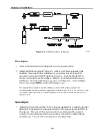
1. Periodically challenging the Model 48C with zero air. The output of the zero air
supply should be greater than the flow demand of the Model 48C. In addition, an
atmospheric dump bypass should be utilized to ensure that the zero air gas flow is
being delivered at atmospheric pressure. Record the Model 48C's response in
percent of scale as A
O
. Compute the zero drift from the following equation:
=
%
Drift
Zero
A
O
- Z
where Z is the recorder response obtained at the last calibration for zero air, % scale.
Summary of Contents for 48C
Page 4: ......
Page 12: ......
Page 14: ......
Page 18: ......
Page 27: ...Chapter 3 Operation 3 3 Figure 3 2 Flowchart of Menu Driven Software ...
Page 112: ......
Page 116: ......
Page 120: ......
Page 123: ...Chapter 7 Servicing 7 3 Figure 7 2 Model 48C Component Layout 48P737 ...
Page 125: ...Chapter 7 Servicing 7 5 Figure 7 3 Optical Bench Exploded View 42P761 ...
Page 138: ......
Page 146: ...Chapter 9 Optional Equipment 9 2 Figure 9 2 Model 48C Dimensional Outline D42P725 ...
Page 155: ...Chapter 9 Optional Equipment Figure 9 8 Purge Housing Assembly 9 11 ...
Page 158: ......
Page 178: ...Appendix B RS 232 Commands B 20 µ ...
Page 184: ......
Page 186: ...C 2 ...
Page 187: ...C 3 ...
Page 188: ...C 4 ...
Page 189: ...C 5 ...
Page 190: ...C 6 ...
Page 191: ...C 7 ...
Page 192: ...C 8 ...
Page 193: ...C 9 ...
Page 194: ...C 10 ...
Page 195: ...C 11 ...
Page 196: ...C 12 ...
Page 197: ...C 13 ...
Page 198: ...C 14 ...
Page 199: ...C 15 ...
Page 200: ......
Page 201: ...APPENDIX D PUMP MAINTENANCE ...
Page 202: ......
Page 203: ......
Page 204: ......


