Chapter 3 Operation
3-2
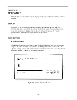
Menu Pushbutton
The
MENU
pushbutton is used to display the Main Menu and to display submenus. When
in the Run screen, this pushbutton displays the Main Menu. When in any other screen, a
submenu is displayed. For more information about the Main Menu, see “Main Menu”
later in this chapter.
Enter Pushbutton
The
ENTER
pushbutton is used to choose a menu item, complete an entry, and toggle
on/off functions.
Help Pushbutton
The
HELP
pushbutton is context-sensitive, that is, it provides additional information about
the screen that is being displayed. Press the
HELP
pushbutton for a concise explanation
about the current screen or menu. Help messages are displayed using lower case letters to
easily distinguish them from the operating screens. To exit a help screen, press
MENU
to
return to the previous screen or
RUN
to return to the Run screen.
↑
↓
←
→
Pushbuttons
The four arrow pushbuttons (
↑
,
↓
,
←
, and
→
) move the cursor up, down, right, and left.
SOFTWARE OVERVIEW
The Model 48C is based on menu-driven software as illustrated by the flowchart in
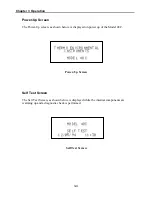
Figure 3-2. The Power-Up and Self Test screens, shown at the top of the flowchart, are
displayed each time the instrument is turned on. These screens are displayed while the
instrument is warming up and performing self-checks. After the warm-up period the Run
screen is automatically displayed. The Run screen is the normal operating screen, it is
where the CO concentration is displayed. From the Run screen, the Main Menu can be
displayed by pressing the
MENU
pushbutton. The Main Menu contains a list of
submenus. Each submenu contains related instrument parameters and/or functions. This
chapter describes each submenu and screen in detail. Refer to the appropriate sections for
more information.
Summary of Contents for 48C
Page 4: ......
Page 12: ......
Page 14: ......
Page 18: ......
Page 27: ...Chapter 3 Operation 3 3 Figure 3 2 Flowchart of Menu Driven Software ...
Page 112: ......
Page 116: ......
Page 120: ......
Page 123: ...Chapter 7 Servicing 7 3 Figure 7 2 Model 48C Component Layout 48P737 ...
Page 125: ...Chapter 7 Servicing 7 5 Figure 7 3 Optical Bench Exploded View 42P761 ...
Page 138: ......
Page 146: ...Chapter 9 Optional Equipment 9 2 Figure 9 2 Model 48C Dimensional Outline D42P725 ...
Page 155: ...Chapter 9 Optional Equipment Figure 9 8 Purge Housing Assembly 9 11 ...
Page 158: ......
Page 178: ...Appendix B RS 232 Commands B 20 µ ...
Page 184: ......
Page 186: ...C 2 ...
Page 187: ...C 3 ...
Page 188: ...C 4 ...
Page 189: ...C 5 ...
Page 190: ...C 6 ...
Page 191: ...C 7 ...
Page 192: ...C 8 ...
Page 193: ...C 9 ...
Page 194: ...C 10 ...
Page 195: ...C 11 ...
Page 196: ...C 12 ...
Page 197: ...C 13 ...
Page 198: ...C 14 ...
Page 199: ...C 15 ...
Page 200: ......
Page 201: ...APPENDIX D PUMP MAINTENANCE ...
Page 202: ......
Page 203: ......
Page 204: ......


