CHAPTER 2
INSTALLATION
The installation of the Model 48C includes lifting the instrument, unpacking the
instrument, connecting sample and exhaust lines to the instrument, and attaching the
analog outputs to a recording device. For more information about optional equipment,
see Chapter 9, “Optional Equipment.”
LIFTING
A procedure appropriate to lifting a heavy object should be used when lifting the
analyzer. This procedure consists of bending at the knees while keeping your back
straight and upright. The analyzer should be grasped at the bottom, in the front and at the
rear of the unit. Do not attempt to lift the analyzer by the cover or other external fittings.
While one person may lift the unit, it is desirable to have two persons lifting, one by
grasping the bottom in the front and the other by grasping the bottom in the rear.
UNPACKING
The Model 48C is shipped complete in one container. If, upon receipt of the analyzer,
there is obvious damage to the shipping container, notify the carrier immediately and
hold for inspection. The carrier, and not Thermo Environmental Instruments Inc., is
responsible for any damage incurred during shipment. Follow the procedure below to
unpack and inspect the instrument.
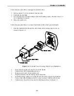
1. Remove the instrument from the shipping container and set on a table or bench that
allows easy access to both the front and rear of the instrument.
2. Remove the instrument cover to expose the internal components.
3. Remove any packing material.
4. Check for possible damage during shipment.
5. Check that all connectors and printed circuit boards are firmly attached.
6. Re-install the instrument cover.
SETUP PROCEDURE
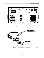
1. Connect the sample line to the
SAMPLE
bulkhead on the rear panel (see Figure 2-1).
Ensure that the sample line is not contaminated by dirty, wet or incompatible
materials. All tubing should be constructed of FEP Teflon
, 316 stainless steel,
borosilicate glass, or similar tubing with an OD of 1/4" and a minimum ID of 1/8".
The length of the tubing should be less than 10 feet.
2-1
Summary of Contents for 48C
Page 4: ......
Page 12: ......
Page 14: ......
Page 18: ......
Page 27: ...Chapter 3 Operation 3 3 Figure 3 2 Flowchart of Menu Driven Software ...
Page 112: ......
Page 116: ......
Page 120: ......
Page 123: ...Chapter 7 Servicing 7 3 Figure 7 2 Model 48C Component Layout 48P737 ...
Page 125: ...Chapter 7 Servicing 7 5 Figure 7 3 Optical Bench Exploded View 42P761 ...
Page 138: ......
Page 146: ...Chapter 9 Optional Equipment 9 2 Figure 9 2 Model 48C Dimensional Outline D42P725 ...
Page 155: ...Chapter 9 Optional Equipment Figure 9 8 Purge Housing Assembly 9 11 ...
Page 158: ......
Page 178: ...Appendix B RS 232 Commands B 20 µ ...
Page 184: ......
Page 186: ...C 2 ...
Page 187: ...C 3 ...
Page 188: ...C 4 ...
Page 189: ...C 5 ...
Page 190: ...C 6 ...
Page 191: ...C 7 ...
Page 192: ...C 8 ...
Page 193: ...C 9 ...
Page 194: ...C 10 ...
Page 195: ...C 11 ...
Page 196: ...C 12 ...
Page 197: ...C 13 ...
Page 198: ...C 14 ...
Page 199: ...C 15 ...
Page 200: ......
Page 201: ...APPENDIX D PUMP MAINTENANCE ...
Page 202: ......
Page 203: ......
Page 204: ......


