Chapter 3 Operation
3-8
There are two ranges, high CO range and low CO range, that correspond to the high CO
and low CO analog outputs, respectively. There are two span coefficients so that each
range can be calibrated separately. This may be necessary if the two ranges are not close
to one another. For example, the low CO range is set to 0-50 ppm and the high CO range
is set to 0-1000 ppm. To use the dual range mode, set option switch 4 on and option
switch 5 off. For more information about setting the internal option switches, see
“Internal Option Switches,” later in this chapter. This enables the sample concentration
reading to be sent to the analog outputs at two different ranges.
Autorange Mode
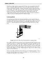
The autorange mode switches the CO analog output between their respective high and
low ranges, depending on the concentration level. The high and low ranges are defined in
the Range menu. The CO analog output has a corresponding status output, as shown in
Figure 3-5. The status outputs are used to indicate which range, high or low, is being
used.
42P943-1
Figure
3-5
. Pin-Out of Rear Panel Terminal Strip in Autorange Mode
For example, suppose the low CO range is set to 50 ppm and the high CO range is set to
100 ppm (see Figure 3-6). Sample concentrations below 50 ppb are presented to the CO
analog output using the low CO range. Sample concentration above 50 ppm are
presented to the CO analog output using the high CO range. The CO status output
indicates which range the CO analog output is using. When the low CO range is active,
the CO status output is at 0 volts. When the high CO range is active, the CO status
output is at 50% of full-scale.
There are two span coefficients so that each range can be calibrated separately. This is
necessary if the two ranges are not close to one another, e.g., if the low NO range is set to
50 ppm and the high range is set to 100 ppm.
Summary of Contents for 48C
Page 4: ......
Page 12: ......
Page 14: ......
Page 18: ......
Page 27: ...Chapter 3 Operation 3 3 Figure 3 2 Flowchart of Menu Driven Software ...
Page 112: ......
Page 116: ......
Page 120: ......
Page 123: ...Chapter 7 Servicing 7 3 Figure 7 2 Model 48C Component Layout 48P737 ...
Page 125: ...Chapter 7 Servicing 7 5 Figure 7 3 Optical Bench Exploded View 42P761 ...
Page 138: ......
Page 146: ...Chapter 9 Optional Equipment 9 2 Figure 9 2 Model 48C Dimensional Outline D42P725 ...
Page 155: ...Chapter 9 Optional Equipment Figure 9 8 Purge Housing Assembly 9 11 ...
Page 158: ......
Page 178: ...Appendix B RS 232 Commands B 20 µ ...
Page 184: ......
Page 186: ...C 2 ...
Page 187: ...C 3 ...
Page 188: ...C 4 ...
Page 189: ...C 5 ...
Page 190: ...C 6 ...
Page 191: ...C 7 ...
Page 192: ...C 8 ...
Page 193: ...C 9 ...
Page 194: ...C 10 ...
Page 195: ...C 11 ...
Page 196: ...C 12 ...
Page 197: ...C 13 ...
Page 198: ...C 14 ...
Page 199: ...C 15 ...
Page 200: ......
Page 201: ...APPENDIX D PUMP MAINTENANCE ...
Page 202: ......
Page 203: ......
Page 204: ......


