Chapter 4 Calibration
4-4
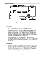
Figure
4-1
. Calibration Flow Schematic
B42P807
Zero Adjust
1. Allow sufficient time for the Model 48C to warm up and stabilize.
2. Adjust the dilution system of Figure 4-1 so that zero air alone is present in the
manifold. Since not all flow controllers have a positive shut off, it might be
necessary to disconnect the CO input line and cap it. Allow the Model 48C to
sample zero air until a stable reading is obtained. From the Main Menu choose
Calibration. From the Calibration menu choose Calibrate Zero. In the Calibrate
Zero screen, press
ENTER
to set the CO reading to zero.
If a strip chart recorder is used to obtain a record of the analog output, it is
recommended that the system be adjusted to obtain a zero trace at 5% of scale. This
is to allow observation of zero drift and/or zero noise. Record the stable zero air
response as Z.
Span Adjust
1. Adjust the zero air flow and the CO flow from the standard CO cylinder to provide a
diluted CO concentration of approximately 80% of the upper range limit (URL) of
the analyzer. The total air flow must exceed the total demand of the analyzer
connected to the output manifold to ensure that no ambient air is pulled into the
manifold vent. The exact CO concentration is calculated from:
Summary of Contents for 48C
Page 4: ......
Page 12: ......
Page 14: ......
Page 18: ......
Page 27: ...Chapter 3 Operation 3 3 Figure 3 2 Flowchart of Menu Driven Software ...
Page 112: ......
Page 116: ......
Page 120: ......
Page 123: ...Chapter 7 Servicing 7 3 Figure 7 2 Model 48C Component Layout 48P737 ...
Page 125: ...Chapter 7 Servicing 7 5 Figure 7 3 Optical Bench Exploded View 42P761 ...
Page 138: ......
Page 146: ...Chapter 9 Optional Equipment 9 2 Figure 9 2 Model 48C Dimensional Outline D42P725 ...
Page 155: ...Chapter 9 Optional Equipment Figure 9 8 Purge Housing Assembly 9 11 ...
Page 158: ......
Page 178: ...Appendix B RS 232 Commands B 20 µ ...
Page 184: ......
Page 186: ...C 2 ...
Page 187: ...C 3 ...
Page 188: ...C 4 ...
Page 189: ...C 5 ...
Page 190: ...C 6 ...
Page 191: ...C 7 ...
Page 192: ...C 8 ...
Page 193: ...C 9 ...
Page 194: ...C 10 ...
Page 195: ...C 11 ...
Page 196: ...C 12 ...
Page 197: ...C 13 ...
Page 198: ...C 14 ...
Page 199: ...C 15 ...
Page 200: ......
Page 201: ...APPENDIX D PUMP MAINTENANCE ...
Page 202: ......
Page 203: ......
Page 204: ......


