Chapter 4 Calibration
4-3
Pressure Regulator for CO Standard Cylinder
The regulator used must have a nonreactive diaphragm and internal parts, as well as a
suitable delivery pressure.
Mixing Chamber
A chamber constructed of glass, Teflon, or other nonreactive material, and designed to
provide thorough mixing of CO and diluent air for the dilution method is required.
Output Manifold
The output manifold should be constructed of glass, Teflon, or other nonreactive material,
and should be of sufficient diameter to ensure an insignificant pressure drop at the
analyzer connection. The system must have a vent designed to ensure atmospheric
pressure at the manifold and to prevent ambient air from entering the manifold.
PRE-CALIBRATION
Prior to calibration, be sure the Model 48C is operating properly. The Model 48C's
internal diagnostics makes this a quick and simple process. Turn on the instrument and
allow it to stabilize for one hour. Perform the service checks of Chapter 5 “Preventive
Maintenance.” Select the operating range and the averaging time of the Model 48C.
CALIBRATION
Connect Instrument
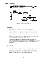
Connect the Model 48C to be calibrated, and the calibration equipment as shown in
Figure 4-1. If an optional sample line filter is used, the calibration must be performed
through this filter. Ensure that the flow rate into the output manifold is greater than the
total flow required by the analyzer and any other flow demand connected to the manifold.
Summary of Contents for 48C
Page 4: ......
Page 12: ......
Page 14: ......
Page 18: ......
Page 27: ...Chapter 3 Operation 3 3 Figure 3 2 Flowchart of Menu Driven Software ...
Page 112: ......
Page 116: ......
Page 120: ......
Page 123: ...Chapter 7 Servicing 7 3 Figure 7 2 Model 48C Component Layout 48P737 ...
Page 125: ...Chapter 7 Servicing 7 5 Figure 7 3 Optical Bench Exploded View 42P761 ...
Page 138: ......
Page 146: ...Chapter 9 Optional Equipment 9 2 Figure 9 2 Model 48C Dimensional Outline D42P725 ...
Page 155: ...Chapter 9 Optional Equipment Figure 9 8 Purge Housing Assembly 9 11 ...
Page 158: ......
Page 178: ...Appendix B RS 232 Commands B 20 µ ...
Page 184: ......
Page 186: ...C 2 ...
Page 187: ...C 3 ...
Page 188: ...C 4 ...
Page 189: ...C 5 ...
Page 190: ...C 6 ...
Page 191: ...C 7 ...
Page 192: ...C 8 ...
Page 193: ...C 9 ...
Page 194: ...C 10 ...
Page 195: ...C 11 ...
Page 196: ...C 12 ...
Page 197: ...C 13 ...
Page 198: ...C 14 ...
Page 199: ...C 15 ...
Page 200: ......
Page 201: ...APPENDIX D PUMP MAINTENANCE ...
Page 202: ......
Page 203: ......
Page 204: ......


