Chapter 7 Servicing
7-12
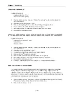
CAPILLARY REMOVAL
Equipment required:
Capillary (Part No 7336)
Wire to clean old capillary
1. Wear an antistatic wrist strap, see “Safety Precautions,” earlier in this chapter for
more information.
2. Disconnect power and remove cover.
3. Remove the capillary from the inlet elbow fitting on the pump head.
4. Clean with less than 0.015" diameter wire or replace.
5. Install the capillary by following the above directions in reverse.
6. Re-install the instrument cover.
OPTIONAL ZERO/SPAN AND SAMPLE SOLENOID VALVE REPLACEMENT
Equipment required:
Solenoid Valve (Part No. 7368)
Screwdriver
Wrench - 9/16"
1. Wear an antistatic wrist strap, see “Safety Precautions,” earlier in this chapter for
more information.
2. Disconnect power and remove cover.
3. Unplug the solenoid from Main Power Supply Board.
4. Remove Teflon
®
lines from solenoid.
5. Remove both screws holding the solenoid to the rear panel.
6. Install the solenoid by following the above directions in reverse.
7. Re-install the instrument cover.
8. Perform a leak test as described in Chapter 5, “Preventive Maintenance.”
ANALOG OUTPUT ADJUSTMENT
The analog outputs need only be adjusted if the concentration value on the front panel
display disagrees with the analog outputs. To see if the analog outputs need to be
adjusted, compare the front panel display to the analog output voltage. If they differ by
more than 1%, then the analog outputs should be adjusted. This procedure should only be
performed by an instrument service technician.
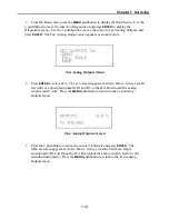
1. Wear an antistatic wrist strap that is properly connected to earth ground, see “Safety
Precautions,” earlier in this chapter for more information.
2. Remove the instrument cover.
Summary of Contents for 48C
Page 4: ......
Page 12: ......
Page 14: ......
Page 18: ......
Page 27: ...Chapter 3 Operation 3 3 Figure 3 2 Flowchart of Menu Driven Software ...
Page 112: ......
Page 116: ......
Page 120: ......
Page 123: ...Chapter 7 Servicing 7 3 Figure 7 2 Model 48C Component Layout 48P737 ...
Page 125: ...Chapter 7 Servicing 7 5 Figure 7 3 Optical Bench Exploded View 42P761 ...
Page 138: ......
Page 146: ...Chapter 9 Optional Equipment 9 2 Figure 9 2 Model 48C Dimensional Outline D42P725 ...
Page 155: ...Chapter 9 Optional Equipment Figure 9 8 Purge Housing Assembly 9 11 ...
Page 158: ......
Page 178: ...Appendix B RS 232 Commands B 20 µ ...
Page 184: ......
Page 186: ...C 2 ...
Page 187: ...C 3 ...
Page 188: ...C 4 ...
Page 189: ...C 5 ...
Page 190: ...C 6 ...
Page 191: ...C 7 ...
Page 192: ...C 8 ...
Page 193: ...C 9 ...
Page 194: ...C 10 ...
Page 195: ...C 11 ...
Page 196: ...C 12 ...
Page 197: ...C 13 ...
Page 198: ...C 14 ...
Page 199: ...C 15 ...
Page 200: ......
Page 201: ...APPENDIX D PUMP MAINTENANCE ...
Page 202: ......
Page 203: ......
Page 204: ......


