Chapter 3 Operation
3-43
Zero.
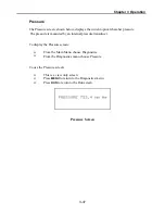
The Zero screen, as shown below, sets the analog outputs to zero volts.
Use the
↑
and
↓
pushbuttons to increment/decrement the output level. For
example, to set the analog outputs to 5%, use the
↑
pushbutton to increment the
0.0 to 5.0%.
To display the Zero screen:
From the Main Menu choose Diagnostics
From the Diagnostics menu choose Test Analog Outputs
From the Test Analog Outputs menu choose Zero
To use the Zero screen:
Use the
↑
and
↓
pushbuttons to increment/decrement the output level
Press
MENU
to return to the Diagnostics menu and cancel the zero output
Press
RUN
to return to the Run screen and cancel the zero output
Zero Analog Outputs Screen
Summary of Contents for 48C
Page 4: ......
Page 12: ......
Page 14: ......
Page 18: ......
Page 27: ...Chapter 3 Operation 3 3 Figure 3 2 Flowchart of Menu Driven Software ...
Page 112: ......
Page 116: ......
Page 120: ......
Page 123: ...Chapter 7 Servicing 7 3 Figure 7 2 Model 48C Component Layout 48P737 ...
Page 125: ...Chapter 7 Servicing 7 5 Figure 7 3 Optical Bench Exploded View 42P761 ...
Page 138: ......
Page 146: ...Chapter 9 Optional Equipment 9 2 Figure 9 2 Model 48C Dimensional Outline D42P725 ...
Page 155: ...Chapter 9 Optional Equipment Figure 9 8 Purge Housing Assembly 9 11 ...
Page 158: ......
Page 178: ...Appendix B RS 232 Commands B 20 µ ...
Page 184: ......
Page 186: ...C 2 ...
Page 187: ...C 3 ...
Page 188: ...C 4 ...
Page 189: ...C 5 ...
Page 190: ...C 6 ...
Page 191: ...C 7 ...
Page 192: ...C 8 ...
Page 193: ...C 9 ...
Page 194: ...C 10 ...
Page 195: ...C 11 ...
Page 196: ...C 12 ...
Page 197: ...C 13 ...
Page 198: ...C 14 ...
Page 199: ...C 15 ...
Page 200: ......
Page 201: ...APPENDIX D PUMP MAINTENANCE ...
Page 202: ......
Page 203: ......
Page 204: ......


