Chapter 3 Operation
3-15
AVERAGING TIME
The averaging time defines a time period (1 to 300 seconds) during which CO
measurements are taken. The average concentration of the readings are calculated for that
time period. The front panel display and analog outputs are updated every 10 seconds for
averaging times between 10 and 300 seconds. For averaging times of 1, 2, and 5 seconds,
the front panel display and analog outputs are updated every second. An averaging time
of 10 seconds, for example, means that the average concentration of the last 10 seconds
will be output at each update. An averaging time of 300 seconds means that the moving
average concentration of the last 300 seconds will be output at each update. Therefore,
the lower the averaging time the faster the front panel display and analog outputs respond
to concentration changes. Longer averaging times are typically used to smooth output
data.
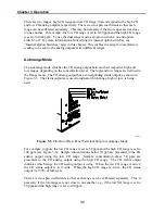
The Averaging Time screens for the single and dual or auto range modes are shown
below. In the dual and auto range modes, an Averaging Time Menu is displayed before
the averaging time screens. This menu is needed because the dual and auto range modes
have two averaging times (high and low). The Averaging Time screens function the same
way in the single, dual, and autorange modes. The following averaging times are
available: 1, 2, 5, 10, 20, 30, 60, 90, 120, 180, 240, and 300 seconds.
To display the Averaging Time menu/screen:
From the Main Menu Choose Averaging Time
To use the Averaging Time screen:
In Dual or Auto range select Hi or Lo average in single range proceed to next step
Use the
↑
and
↓
pushbuttons to select the averaging time
Press
ENTER
to accept the averaging time
Press
MENU
to return to the Main Menu
Press
RUN
to return to the Run screen
Single and Dual/Auto Mode Averaging Time Screens
AVG TIME 10 SEC
SET TO 10 SEC
78
SELECT
AVERAGING TIME:
>HI AVG TIME 300 SEC
LO AVG TIME 300 SEC
HI AVG TIME 30 SEC
SET TO 30 SEC
78
SELECT
Summary of Contents for 48C
Page 4: ......
Page 12: ......
Page 14: ......
Page 18: ......
Page 27: ...Chapter 3 Operation 3 3 Figure 3 2 Flowchart of Menu Driven Software ...
Page 112: ......
Page 116: ......
Page 120: ......
Page 123: ...Chapter 7 Servicing 7 3 Figure 7 2 Model 48C Component Layout 48P737 ...
Page 125: ...Chapter 7 Servicing 7 5 Figure 7 3 Optical Bench Exploded View 42P761 ...
Page 138: ......
Page 146: ...Chapter 9 Optional Equipment 9 2 Figure 9 2 Model 48C Dimensional Outline D42P725 ...
Page 155: ...Chapter 9 Optional Equipment Figure 9 8 Purge Housing Assembly 9 11 ...
Page 158: ......
Page 178: ...Appendix B RS 232 Commands B 20 µ ...
Page 184: ......
Page 186: ...C 2 ...
Page 187: ...C 3 ...
Page 188: ...C 4 ...
Page 189: ...C 5 ...
Page 190: ...C 6 ...
Page 191: ...C 7 ...
Page 192: ...C 8 ...
Page 193: ...C 9 ...
Page 194: ...C 10 ...
Page 195: ...C 11 ...
Page 196: ...C 12 ...
Page 197: ...C 13 ...
Page 198: ...C 14 ...
Page 199: ...C 15 ...
Page 200: ......
Page 201: ...APPENDIX D PUMP MAINTENANCE ...
Page 202: ......
Page 203: ......
Page 204: ......

