Chapter 3 Operation
3-5
Run Screen
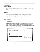
The standard Run screen, as shown below, displays the CO concentration. It also
displays time and the status of the RS-232 interface and optional zero/span and sample
solenoid valves, if installed. The word “Sample” on the bottom left of the display
indicates the analyzer has the span/zero valve option and is in “SAMPLE” mode. Other
modes appear in the same area of the display as “ZERO” or” SPAN”. For more
information about the optional solenoid valves see Chapter 9, “Optional Equipment.” In
dual or auto range mode two simultaneous calculations are performed. One uses the
coefficients associated with the low range producing the low range concentration and the
other uses the coefficients associated with the high range producing the high range
concentration. The “l” preceding “CO PPM” indicates that the low concentration is
displayed. To display the high concentration press the
↑
pushbutton. To display the low
concentration press the
↓
pushbutton.
Run Screen
Main Menu
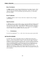
The Main Menu contains several submenus as shown below. Instrument parameters and
features are divided into these submenus according to their function. Use the
↑
and
↓
pushbuttons to move the cursor to each submenu. Use the
ENTER
pushbutton to select a
submenu. The last menu item
SERVICE
appears only in the service mode.
Main
Menu
CALIBRATION
INSTRUMENT
CONTROLS
DIAGNOSTICS
ALARM
SERVICE
Main Menu
lCO PPM 25.5
SAMPLE 10:25 REMOTE
MAIN MENU: 10:25
>RANGE
AVERAGING TIME
CALIBRATION FACTORS
Summary of Contents for 48C
Page 4: ......
Page 12: ......
Page 14: ......
Page 18: ......
Page 27: ...Chapter 3 Operation 3 3 Figure 3 2 Flowchart of Menu Driven Software ...
Page 112: ......
Page 116: ......
Page 120: ......
Page 123: ...Chapter 7 Servicing 7 3 Figure 7 2 Model 48C Component Layout 48P737 ...
Page 125: ...Chapter 7 Servicing 7 5 Figure 7 3 Optical Bench Exploded View 42P761 ...
Page 138: ......
Page 146: ...Chapter 9 Optional Equipment 9 2 Figure 9 2 Model 48C Dimensional Outline D42P725 ...
Page 155: ...Chapter 9 Optional Equipment Figure 9 8 Purge Housing Assembly 9 11 ...
Page 158: ......
Page 178: ...Appendix B RS 232 Commands B 20 µ ...
Page 184: ......
Page 186: ...C 2 ...
Page 187: ...C 3 ...
Page 188: ...C 4 ...
Page 189: ...C 5 ...
Page 190: ...C 6 ...
Page 191: ...C 7 ...
Page 192: ...C 8 ...
Page 193: ...C 9 ...
Page 194: ...C 10 ...
Page 195: ...C 11 ...
Page 196: ...C 12 ...
Page 197: ...C 13 ...
Page 198: ...C 14 ...
Page 199: ...C 15 ...
Page 200: ......
Page 201: ...APPENDIX D PUMP MAINTENANCE ...
Page 202: ......
Page 203: ......
Page 204: ......

