


4. Fuel Injection System
4-44
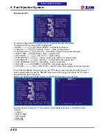
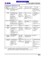
Fault Code and Warning Lamp Flashing Identification Table
No.
Fault
codes
Fault Description
Check
light
Check light flashing
state
Parts Inspection
Throttle position sensor fault
Lighting
long 0
,
short 6
Throttle position sensor and wire
1
0120
Fault detection procedures Please refer to the "EFI System components description" throttle position sensor
(TPS) chapter
Manifold Absolute Pressure sensor fault lighting
long 0
,
short 9
MAP sensorand wire
2
0105
Fault detection procedures Please refer to the "EFI System components description" manifold Absolute
Pressure sensor (MAP) chapter
Engine temperature sensor fault (water) lighting
long 1
,
short 2
Engine temperature sensor and wire
3
0115
Fault detection procedures Please refer to the "EFI System components description" engine temperature
sensor (WPS) chapter.
Engine oil temperature sensor fault (oil) lighting
long 1
,
short 1
Engine temperature sensor and wire
4
0195
The current reservation
Intake air temperature sensor fault
lighting
long 1
,
short 3
Intake temperature sensor and wire
5
0110
Fault detection procedures Please refer to the "EFI System components description" intake temperature
sensor (TAS) chapter.
Roll over sensor fault
lighting
long 1
,
short 5
Roll over sensor and wire
6
1630
Fault detection procedures Please refer to the "EFI System components description" Roll over sensor chapter.
O
2
sensor fault
lighting
long 1
,
short 7
O
2
Sensorand wire
7
0130
Fault detection procedures Please refer to the "EFI System components description" O
2
sensor chapter.
INJ
#1 fault
lighting
long 3
,
short 3
Injector and wire
8
0201
Fault detection procedures Please refer to the "EFI System components description" fuel injector chapter.
IG #1 fault
lighting
long 3
,
short 7
Ignition coil and wire
9
0351
Fault detection procedures to adhere to the traditional way
Fuel pump fault
lighting
long 4
,
short 1
Fuel pump and wire
10
0230
Fault detection procedures Please refer to the "EFI System components description" fuel pump chapter.
O
2
sensor heater fault
lighting
long 4
,
short 5
O
2
Sensorand wire
11
0135
Fault detection procedures Please refer to the "EFI System components description" O
2
Sensor chapter.
ISC motor fault
lighting
long 4
,
short 9
Stepper motor and wire
12
1505
Fault detection procedures Please refer to the "EFI System components description" idle speed control valve
(ISC) chapter.
Exhaust 2
nd
air solenoid valve fault
lighting
long 5
,
short 4
2
nd
air control valve and wire
13
1410
Fault detection procedures Please refer to the "EFI System components description" 2
nd
air solenoid valve
chapter.
Crankshaft position sensor fault
lighting
long 6
,
short 6
Crankshaft position sensor and wire
14
0335
Fault detection procedures Please refer to the "EFI System components description" Crankshaft position
sensor chapter.
PM wire fault
lighting
long 6
,
short 8
Manifold absolute pressure sensor
and wire
15
1205
Fault detection procedures Please refer to the "EFI System components description" Manifold absolute
pressure sensor (MAP) chapter.
EEPROM fault
Not lit
long –
,
short –
EEPROM
16
0603
Replace ECU
To this chapter contents
Summary of Contents for Citycom.300i
Page 5: ...Serial Number Home page Contents...
Page 38: ...2 Maintenance Information 2 17 Note To this chapter contents...
Page 46: ...3 LUBRICATION SYSTEM 3 8 Notes To this chapter contents...
Page 106: ...4 Fuel Injection System 4 60 Note To this chapter contents...
Page 173: ...10 AC Generator Starting Clutch 10 10 Notes To this chapter contents...
Page 195: ...12 Cooling System 12 14 Notes To this chapter contents...
Page 223: ...14 Brake System 14 12 Note To this chapter contents...
Page 244: ...17 Electrical System 17 5 FUSE Fuse circuit diagram To this chapter contents...
Page 262: ...17 Electrical System 17 23 Note To this chapter contents...
Page 270: ...19 Electrical Diagram 19 1 Home page Contents LH30W EFi Electrical Diagram 19...