


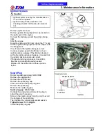


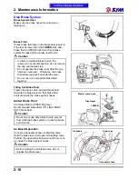


2. Maintenance Information
2-14
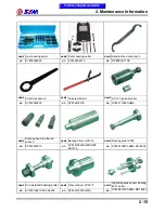
Special Tools List
NAME
Left crank bearing puller
NAME
R/L. crank case disassemble
tool
NAME
Valve cotter remove &
assembly tool
NO
SYM-9100100
NO
SYM-1120000-HMA H9A
NO
SYM-1471110/20
NAME
L. Crank shaft puller
NAME
Clutch special nut socket
NAME
Tappet adjusting
NO
SYM-1130000-HMA H9A
NO
SYM-9020210-HMA
NO
SYM-1472100
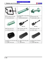
NAME
R. crank case bearing 6201
assembles tool
NAME
Left crankshaft & oil seal
assembly socket.
NAME
Rocker arm shaft disassemble
NO
SYM-9614000-HMA 6201
NO
SYM-1332100-HMA RB1
NO
SYM-1445100
NAME
Bearing driver set
NAME
Assembly directs puller
NAME
Drive shaft puller
NO
SYM-6204024
NO
SYM-2341110
NO
SYM-2341120- HMA RB1
To this chapter contents
Summary of Contents for Citycom.300i
Page 5: ...Serial Number Home page Contents...
Page 38: ...2 Maintenance Information 2 17 Note To this chapter contents...
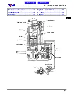
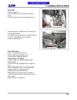
Page 46: ...3 LUBRICATION SYSTEM 3 8 Notes To this chapter contents...
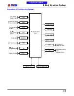
Page 106: ...4 Fuel Injection System 4 60 Note To this chapter contents...
Page 173: ...10 AC Generator Starting Clutch 10 10 Notes To this chapter contents...
Page 195: ...12 Cooling System 12 14 Notes To this chapter contents...
Page 223: ...14 Brake System 14 12 Note To this chapter contents...
Page 244: ...17 Electrical System 17 5 FUSE Fuse circuit diagram To this chapter contents...
Page 262: ...17 Electrical System 17 23 Note To this chapter contents...
Page 270: ...19 Electrical Diagram 19 1 Home page Contents LH30W EFi Electrical Diagram 19...


