


17. Electrical System
17-21
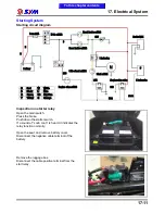
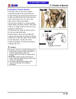
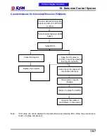
Cooling Fan Thermo Switch
The thermo switch mounted on the radiator
controls the operation of the cooling fan motor.
In case that the fan motor fails to work, disconnect
the green and black/blue leads and connect jump
wires to the terminals, then, turn on the main
switch, the fan motor should operate.
If the fan motor still fails to run, measure battery
voltage between the green and black / blue leads.
If there is no voltage, check for blown fuse, loose
connection or short-circuit.
If the fan motor runs, check the thermo switch in
the manner as described below:
Hang the thermo switch on the bowl filled with
coolant to check the switch’s opening and closing
temperatures, confirm the switch is open circuited
at room temperature, increase the coolant
temperature gradually. The switch should have a
continuity at 95-101
℃
.
Caution
Keep the coolant at a constant temperature at
least for three minutes. Sudden increase the
coolant temperature will cause the
thermometer and the tester to indicate wrong
readings.
Never let the thermometer and the thermo
switch contact the wall of the bowl, which may
result in wrong readings.
The thermo switch shall be placed in the
coolant until the teeth are completely
submerged.
Thermometer
Thermo switch
To this chapter contents
Thermo switch
Summary of Contents for Citycom.300i
Page 5: ...Serial Number Home page Contents...
Page 38: ...2 Maintenance Information 2 17 Note To this chapter contents...
Page 46: ...3 LUBRICATION SYSTEM 3 8 Notes To this chapter contents...
Page 106: ...4 Fuel Injection System 4 60 Note To this chapter contents...
Page 173: ...10 AC Generator Starting Clutch 10 10 Notes To this chapter contents...
Page 195: ...12 Cooling System 12 14 Notes To this chapter contents...
Page 223: ...14 Brake System 14 12 Note To this chapter contents...
Page 244: ...17 Electrical System 17 5 FUSE Fuse circuit diagram To this chapter contents...
Page 262: ...17 Electrical System 17 23 Note To this chapter contents...
Page 270: ...19 Electrical Diagram 19 1 Home page Contents LH30W EFi Electrical Diagram 19...


