


4. Fuel Injection System
4-59
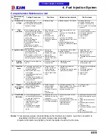
Comprehensive Maintenance List
No.
Maintenance
Project
Testing Procedures
Test items
Determine benchmarks
Fault reasons
1
Power and
voltage
●Use meter direct
measurement battery voltage
●Use diagnosis tool detection
of battery voltage
● Battery voltage
● Battery voltage = 10V Above
● Battery electricity
● Battery connector loose
● Harness circuit opening
● ECU coupler not connected
properly
2
Fuel
pressure
●Use fuel pressure gauge,
connected in series between
the injector and the Pressure
Regulating Valve
●Main switch ON, but not
start engine
●Check fuel pressure
●Start engine (idle)
●Check change of the fuel
pressure
●throttle several rotation
●check to the change of fuel
pressure again
● Open the main
switch, but not to start
the engine of
pressure
● Pressure in idle
● Rotating throttle,
situation of pressure
changes
● Open main switch, but not
srart:
pressure = 250kPa (Stable
value)
● Idle state:
pressure = 294„6kPa
(Beating situation from top to
bottom)
● rotation throttle moment:
pressure = 294„6kPa (Slightly
beating)
● Fuel not enough
● Security switch not disarm
● Ruel pump relay fault
● Ruel pump fault
● Injector fault
● ECU fault
3
Ignition state
●The spark plug removed from
the cylinder head, but the
power lines still ring
●Start engines or use for the
diagnosis tool of output View
spark plug ignition conditions
● Spark plug
specifications
● Whether the spark
plug ignition
● Spark plug sparks
whether it is normal
strength
● Specifications: NGK-CR8H
● Ignition conditions:
With traditional engines found
ways
● Spark plug fault
● Roll over sensor fault
● ECU No. 5 pin fault
● Ignition coil fault
● Crankshaft position sensor
fault
4
Engine
vacuum
●Diagnosis tool to detect the
use of
● Manifold pressure of
diagnosis tool
● Manifold pressure
=32~38kPa
● Valve clearance abnormal
● Intake system leak
5
Injection
state
● The injector removed from
the throttle body, but not
dismantle pipeline
● Main switch ON, but not
start engine
● Investigation the injector it’s
leaking fuel?
● Once again start engines or
use for the diagnosis tool of
output function
● Check injector fuel injection
and the injection situation
● Open the main
switch, but did not
start engine the
injection situation
● Injector state when
start
● Not started, injector not
leaking fuel
● In started, the injection state
must show fan shape
● Security unit is configured
not disarm
● Fuel pump relay fault
● Fuel pump fault
● Injector fault
● ECU fault
6
Closed -
loop control
system
● Use of diagnostic tool
observation O2 Sensor
voltage changes
● Stable condition,
sensor voltage
variation (Idle
continued 5 minutes
later to
measurement)
● Idle stable condition: O2
Sensor voltage = 50 ~ 200mV
(Show from top to bottom
beating phenomenon)
● O2 Sensor fault
● ECU fault
7
Fault Code
Detection
● Use of the diagnosis tool
existing fault-detection code
or historical Fault Code
● Elimination of the
implementation of fault
codes, check can be
eliminated
● Once again start engine
● Check fault is it happen
again
● Diagnosis tool of the
fault code is it can be
eliminated
● Start again, the fault
is it will happen again
● Without any residual Fault
Code
● If residual Fault Code,
according to the "Fault Code
Maintenance Form"
implementation of
troubleshooting
● throttle position sensor fault
● Engine temperature sensor
fault
● Intake temperature sensor
fault
● Manifold pressure sensor
fault
● O2 Sensor fault
● Crankshaft position sensor
fault
● ECU fault
● Roll over sensor fault
Notes:
1.Fuel pressure gauge connected between the fuel tank and injector, open the main switch to
repeatedly shut down, fuel system makes pressure stability.
2.Injector and injector cap tightly by hands, fuel spills should not be the case.
To this chapter contents
Summary of Contents for Citycom.300i
Page 5: ...Serial Number Home page Contents...
Page 38: ...2 Maintenance Information 2 17 Note To this chapter contents...
Page 46: ...3 LUBRICATION SYSTEM 3 8 Notes To this chapter contents...
Page 106: ...4 Fuel Injection System 4 60 Note To this chapter contents...
Page 173: ...10 AC Generator Starting Clutch 10 10 Notes To this chapter contents...
Page 195: ...12 Cooling System 12 14 Notes To this chapter contents...
Page 223: ...14 Brake System 14 12 Note To this chapter contents...
Page 244: ...17 Electrical System 17 5 FUSE Fuse circuit diagram To this chapter contents...
Page 262: ...17 Electrical System 17 23 Note To this chapter contents...
Page 270: ...19 Electrical Diagram 19 1 Home page Contents LH30W EFi Electrical Diagram 19...


