


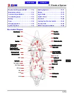


17. Electrical System
17-9
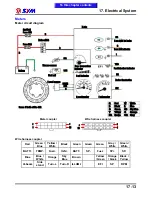
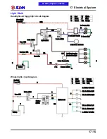
Ignition System
ECU. coupler (ECU. side)
01 pin(R/Y)
:
Drive components Power.
03 pin(G/W)
:
Crankshaft position sensor negative.
09 pin(L/Y)
:
Crankshaft position sensor positive.
18 pin(G/W)
:
Ignition coil driver.
To this chapter contents
ECU
CPS
Roll over sensor
AC. G.
B/Y
L/Y
Ignition coil
R/Y
G/W
R/G
L/W
W/R
B/G
B
R
R
R
G
G
Tachometer
Power relay
Side stand
switch
Main switch
Engine stop
switch
Fuse 20A
Fuse 15A
Battery
GR/L
R/Y
B/O
Summary of Contents for Citycom.300i
Page 5: ...Serial Number Home page Contents...
Page 38: ...2 Maintenance Information 2 17 Note To this chapter contents...
Page 46: ...3 LUBRICATION SYSTEM 3 8 Notes To this chapter contents...
Page 106: ...4 Fuel Injection System 4 60 Note To this chapter contents...
Page 173: ...10 AC Generator Starting Clutch 10 10 Notes To this chapter contents...
Page 195: ...12 Cooling System 12 14 Notes To this chapter contents...
Page 223: ...14 Brake System 14 12 Note To this chapter contents...
Page 244: ...17 Electrical System 17 5 FUSE Fuse circuit diagram To this chapter contents...
Page 262: ...17 Electrical System 17 23 Note To this chapter contents...
Page 270: ...19 Electrical Diagram 19 1 Home page Contents LH30W EFi Electrical Diagram 19...


