4. Fuel Injection System
4-26
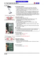
Fuel Pump
Fuel pump & fuel unit coupler plan
Confirmed working voltage
Harness-face coupler plan
Resistance Confirmation
Functional Description:
Powered by DC 8~16V, and has four-pin socket on the pump.
The two terminals are connected to power source and ground
respective. The ECU is to control and manage the operation of fuel
pump through electrical power.
Its major component is a driving fan pump that equipped with a low
electrical consuming DC motor. Powered by 12V voltage and keep
fuel pressure inside the fuel pump in 294„6kpa (about 3 kg / cm
2
).
The fuel pump is located inside of the fuel tank, and installed a filter in
front of its inlet so that can prevent from foreign materials sucking into
the fuel pump to damage it and the fuel injector.
Testing Procedures 1:
Fuel pump working voltage confirmed:
●
Fuel pump coupler to properly (using the probe tool), or can be
removed coupler working voltage measurements (direct
measurement).
●
Open the main switch, but not to start engine.
●
Use "volteg meter" DC stalls (DCV) to check fuel pump voltage.
●
Confirmed working voltage:
Volteg meter negative access to the wire harness fuel pump coupler
2nd pin (Green).
Voltage meter positive access to the wire harness fuel pump coupler
first pin (Black / Purple).
Cautions
●
Conducting fuel pump voltage measurement, if the main switch to
open three seconds after the engine did not started, the ECU will
automatically cut off the fuel pump power supply.
Detection judge 1:
1. Working voltage value:
Above 10V
2. Resistance value:
1.5
‰
0.5
Ω
3. Fuel pressure:
294
‰
6kPa (about 3kg/cm
2
)
Testing Procedures 2:
Resistance Confirmation:
●
Removed coupler on the fuel pump.
●
Use of the "meter"
Ohm stalls, Measurement fuel unit resistance (Yellow /
White & Green).
Detection judge 2:
●
Fuel unit resistance value:
4~107.5
Ω
Y/W
G
G
B/PU
Fuel unit
Fuel pump
Yellow
/ White
Green
Gree
n
Black /
Purple
Fuel pump
To this chapter contents
Fuel unit
Summary of Contents for Citycom.300i
Page 5: ...Serial Number Home page Contents...
Page 38: ...2 Maintenance Information 2 17 Note To this chapter contents...
Page 46: ...3 LUBRICATION SYSTEM 3 8 Notes To this chapter contents...
Page 106: ...4 Fuel Injection System 4 60 Note To this chapter contents...
Page 173: ...10 AC Generator Starting Clutch 10 10 Notes To this chapter contents...
Page 195: ...12 Cooling System 12 14 Notes To this chapter contents...
Page 223: ...14 Brake System 14 12 Note To this chapter contents...
Page 244: ...17 Electrical System 17 5 FUSE Fuse circuit diagram To this chapter contents...
Page 262: ...17 Electrical System 17 23 Note To this chapter contents...
Page 270: ...19 Electrical Diagram 19 1 Home page Contents LH30W EFi Electrical Diagram 19...


