


6
. Cylinder Head / Valve
6-5
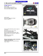
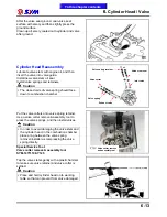
Remove the side cover mounting blots of cylinder
head, and then take out the side cover.
Remove left crankcase cover, and turn the
Turn the drive face, and align the timing mark on
the sprocket with that of cylinder head, piston is at
TDC position.
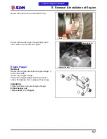
Remove cam sprocket bolts and then remove the
sprocket by prying chain out.
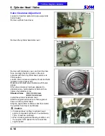
Remove the 2 cylinder head mounting bolts from
cylinder head right side, and then remove 4 nuts
and washers from cylinder head upper side.
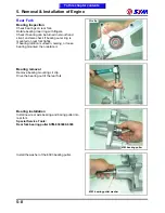
Remove the cylinder head.
Remove cylinder head gasket and 2 dowel pins.
Remove chain guide.
Clean up residues from the matching surfaces of
cylinder and cylinder head.
Caution
Do not damage the matching surfaces of
cylinder and cylinder head.
Avoid residues of gasket or foreign materials
falling into crankcase as cleaning.
To this chapter contents
2 bolts
Timing mark
3 bolts
4 nuts
Bolt •2
Cam chain guide
2 dowel pins
Summary of Contents for Citycom.300i
Page 5: ...Serial Number Home page Contents...
Page 38: ...2 Maintenance Information 2 17 Note To this chapter contents...
Page 46: ...3 LUBRICATION SYSTEM 3 8 Notes To this chapter contents...
Page 106: ...4 Fuel Injection System 4 60 Note To this chapter contents...
Page 173: ...10 AC Generator Starting Clutch 10 10 Notes To this chapter contents...
Page 195: ...12 Cooling System 12 14 Notes To this chapter contents...
Page 223: ...14 Brake System 14 12 Note To this chapter contents...
Page 244: ...17 Electrical System 17 5 FUSE Fuse circuit diagram To this chapter contents...
Page 262: ...17 Electrical System 17 23 Note To this chapter contents...
Page 270: ...19 Electrical Diagram 19 1 Home page Contents LH30W EFi Electrical Diagram 19...


