


6
. Cylinder Head / Valve
6-13
After the valve seat ground, coat valve seat
surface with emery and then slightly press the
ground surface.
Clean up all emery coated onto cylinder and valve
after ground.
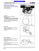
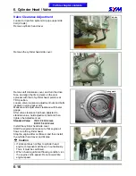
Cylinder Head Reassembly
Lubricate valve stem with engine oil, and then
insert the valve into valve guide.
Install new valve stem oil seal.
Install valve springs and retainers.
Caution
The closed coils of valve spring should face
down to combustion chamber.
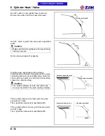
Put the valve cotters onto valve spring retainer.
Use a valve cotter remove & assembly tool to
press the valve springs, and then install valves.
Caution
In order to avoid damaging the valve stem and
the cylinder head, in the combustion chamber
place a rag between the valve spring
remover/installer as compressing the valve
spring directly.
Special Service Tool:
Valve cotter remove & assembly tool
SYM-1471110-SY125
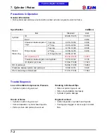
Tap the valve stems gently with a plastic hammer
to make sure valve retainer and valve cotter is
settled.
Caution
Place and hold cylinder head on to working
table so that can prevent from valve damaged.
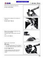
Exhaust valve
Inlet valve
Valve stem seal
Valve spring
Valve spring retainer
Valve cotter
To this chapter contents
Valve cotter remove
and assembly tool
Summary of Contents for Citycom.300i
Page 5: ...Serial Number Home page Contents...
Page 38: ...2 Maintenance Information 2 17 Note To this chapter contents...
Page 46: ...3 LUBRICATION SYSTEM 3 8 Notes To this chapter contents...
Page 106: ...4 Fuel Injection System 4 60 Note To this chapter contents...
Page 173: ...10 AC Generator Starting Clutch 10 10 Notes To this chapter contents...
Page 195: ...12 Cooling System 12 14 Notes To this chapter contents...
Page 223: ...14 Brake System 14 12 Note To this chapter contents...
Page 244: ...17 Electrical System 17 5 FUSE Fuse circuit diagram To this chapter contents...
Page 262: ...17 Electrical System 17 23 Note To this chapter contents...
Page 270: ...19 Electrical Diagram 19 1 Home page Contents LH30W EFi Electrical Diagram 19...