


4. Fuel Injection System
4-23
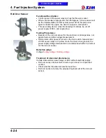
Numerical voltage changes that
the situation.
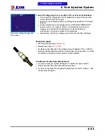
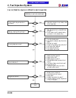
3. Used the diagnosis tool to confirm of O
2
sensor work situations:
●
Connected the "diagnosis tool" to diagnosis coupler and open the
main switch to start the engine.
●
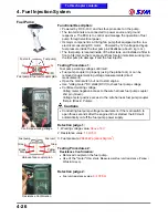
Engine to be completely warm-up (idling state operation "5 minutes"
above).
●
Screen will switch to the diagnosis tool of "DATA STREAM 01/01"
screen, select " O
2
Sensor" project, and switches to a wave of
images, turn the throttle engine speed to about 4500 rpm,
Observation O
2
Sensor actuator circumstances.
●
Observation O
2
Sensor voltage values that the situation changes.
Detection judge:
●
Working voltage value:
above 10V
●
Resistance value:
6.7~10.5
Ω
●
O
2
Sensor amendment in the voltage value of between 100 ~ 900 mV
beating; representatives pollution closed-loop control system to normal,
if contrary to maintain a fixed value for abnormalities.
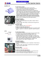
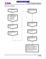
Treatment of abnormal phenomena:
●
O
2
sensor damage, heater damaged or couplers to poor contact.
●
Check whether the abnormal wire harness lines.
●
O
2
Sensor anomaly, the proposed replacement of the O
2
Sensor
,
and
measurements again.
To this chapter contents
Summary of Contents for Citycom.300i
Page 5: ...Serial Number Home page Contents...
Page 38: ...2 Maintenance Information 2 17 Note To this chapter contents...
Page 46: ...3 LUBRICATION SYSTEM 3 8 Notes To this chapter contents...
Page 106: ...4 Fuel Injection System 4 60 Note To this chapter contents...
Page 173: ...10 AC Generator Starting Clutch 10 10 Notes To this chapter contents...
Page 195: ...12 Cooling System 12 14 Notes To this chapter contents...
Page 223: ...14 Brake System 14 12 Note To this chapter contents...
Page 244: ...17 Electrical System 17 5 FUSE Fuse circuit diagram To this chapter contents...
Page 262: ...17 Electrical System 17 23 Note To this chapter contents...
Page 270: ...19 Electrical Diagram 19 1 Home page Contents LH30W EFi Electrical Diagram 19...


