


4. Fuel Injection System
4-6
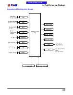
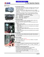
Ignition System Outline
Principle
ECU determines the appropriate ignition timing by receiving the signals from the CPS, TPS, O
2
Sensor,
MAP Sensor, TA Sensor and TW Sensor in accordance with the engine RPM. The ignition coil produces
25000~30000 volts to fire the spark plug, maximizing the engine output, and improving the fuel
comsumption efficiency.
Specifications
1.
Ignition timing: 13 ‚ BTDC / 1650RPM
2.
Spark plug: NGK CR8E Clearance: 0.6 to 0.7 mm
3.
Crankshaft Position Sensor electric resistance: 80 ~ 160 Ω (Green / White - Blue / Yellow)
4.
Ignition coil primary circuit: 2.8 Ω „ 15% (20 ƒ C) (Red / Yellow - Black / Yellow)
5.
Battery Type: YTX12A-BS or GTX12A-BS Capacity: 12V 12Ah
ACG/ Flywheel Gear
(23+1 Long tooth)
CPS
Throttle position
Manifold absolute pressure
Engine coolant temperature
REG. REC.
Ignition coil
S
p
a
rk
p
lu
g
ECU
Oxygen content
Battery
Intake air temperature
Power relay
To this chapter contents
Summary of Contents for Citycom.300i
Page 5: ...Serial Number Home page Contents...
Page 38: ...2 Maintenance Information 2 17 Note To this chapter contents...
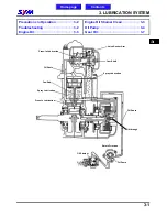
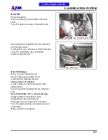
Page 46: ...3 LUBRICATION SYSTEM 3 8 Notes To this chapter contents...
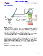
Page 106: ...4 Fuel Injection System 4 60 Note To this chapter contents...
Page 173: ...10 AC Generator Starting Clutch 10 10 Notes To this chapter contents...
Page 195: ...12 Cooling System 12 14 Notes To this chapter contents...
Page 223: ...14 Brake System 14 12 Note To this chapter contents...
Page 244: ...17 Electrical System 17 5 FUSE Fuse circuit diagram To this chapter contents...
Page 262: ...17 Electrical System 17 23 Note To this chapter contents...
Page 270: ...19 Electrical Diagram 19 1 Home page Contents LH30W EFi Electrical Diagram 19...


